Introduction
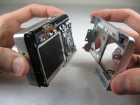
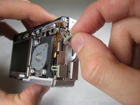
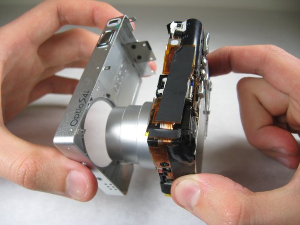
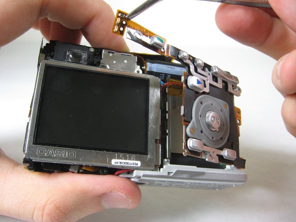
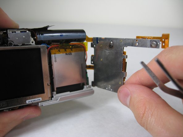
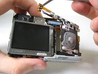
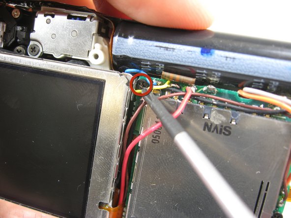
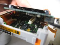
In this guide you will learn how to remove the SD card circuit board to access the logic board. To access the logic board, you will need to unsolder two leads. For soldering instructions, please refer to steps 1 through 6 of this soldering guide.
What you need
-
-
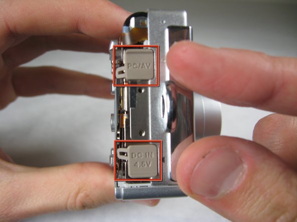
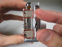
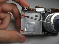
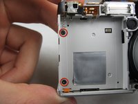
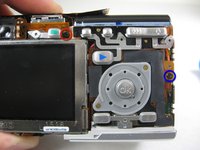
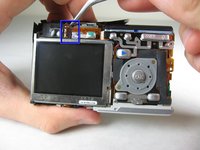
Remove the following screws:
-
Two silver 3.15mm Phillips #00 screws on the right side of the camera
-
Two silver 2.08mm Phillips #00 screws on the left side of the camera
-
-
-
-
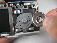
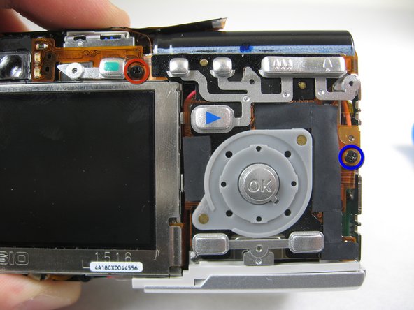
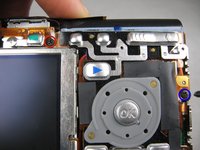
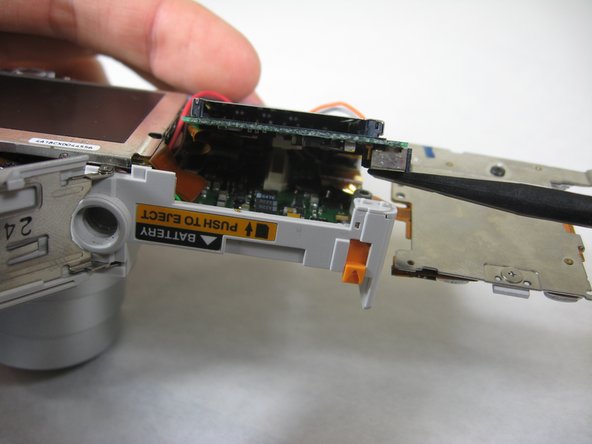
On the front of the camera, in battery case, remove screws indicated:
-
Two black 2.05mm Phillips #00 screws
-


To reassemble your device, follow these instructions in reverse order.
Team

Cal Poly, Team 4-29, Regan Winter 2011 Member of Cal Poly, Team 4-29, Regan Winter 2011
CPSU-REGAN-W11S4G29
3 Members
10 Guides authored