Introduction
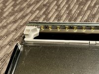
Thunderbolt Display uses an LG edge LED lit LCD Display (also 09-11 27" iMacs and 27" Cinema Displays). The LEDs are on the bottom edge of the display. There are 2 bars (left and right) Each bar has many LEDs and a 6 pin connector. Each pin drive several LEDs thus is the highest current flow / heat junction. The weak lead free solder gradually fails with thermal expansion/contraction cycling and increases resistance. PSU will compensate up to a point, then when the current is too high, PSU just shut down the backlight causing a dark display. I have even seen connector just fell off as solder points became completely detached.
Usually this problem starts manifesting itself with brighter settings only. Can work around by reduce brightness. Eventually, even the lowest brightness won't work anymore.
Another failure mode is when actual LED(s) fail. This require changing the backlight LED bar.
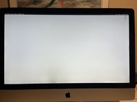
There are several ways to diagnose this. While the screen is lit, turn on sound level change feedback so when screen goes blank, can use vol change feedback to confirm Mac is still running. Also setup a high contrast image (black wall paper, About This Mac popup) to help view the LCD image when backlight goes out (works for iMac, not sure about TB Display)
Use apple keyboard and set brightness to lowest level. Put mac to sleep (option+command+eject) and wake (any key) This will restart the inverter board to see if can drive backlight for longer before inverter board detect over voltage (due to bad solder joint/failed LED) and shut off.
Made a PDF long ago to detail this repair. Largely duplicated in this guide but attached it here (at the end) for additional reference.
What you need
-
-
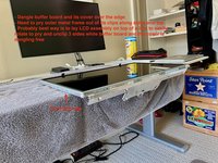
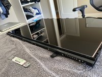
Follow LCD removal guide Additional tip is to put fingers over the tip of the T10 driver to prevent it from slipping off. LCD surface is very soft and will scratch instantly against any metal driver.
-
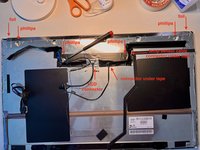
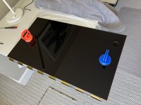
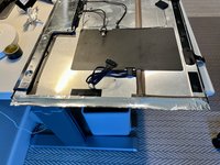
Good to use small box to hold up LCD will disconnecting 4x LCD cables (power, video, temp sensor, and ground wire) See next steps or more pics
-
A small rubberized flash light are grate for placing inside to shine light on a particular area. Corrective lenses essential if have poor eye sight
-
Keep the 8x T-10 screws separate from the other T-10 removed later
-
-
-
Really strong magnets near the 8x LCD mounting screws. And screws can easily fall into the abyss of the iMac. A curved tweezer works well to assist in both removal and reinstall.
-
-
-
More pics on disconnecting LCD cables
-
With LCD propped up by a box, a small flashlight (plastic casing would be best) can help see the connectors.
-
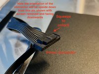
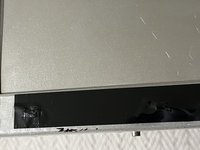
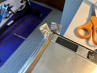
Power connector is the hardest as its under the main board so need to blind disconnect. First remove the clear tape that holds down the cable. Then feel by finger to find the connector, squeeze the lock and pull. See picture for reference (note the picture of the connector is removed and shown upside down for clarity)
-
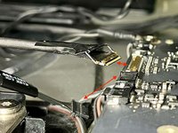
The video connector has a locking latch that must be unclipped. Picture shows a handle tape on this latch. Pull up on tape and unclip the latch before pulling out the connector.
-
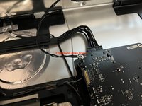
After power, video, and 6pin connector are disconnected. Can tilt the LCD assembly higher (60-70 degrees so nearly vertical) to remove the T-10 ground screw with a driver.
-
-
-
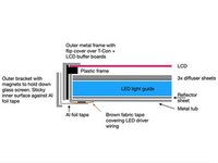
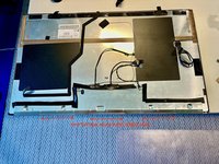
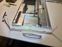
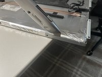
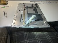
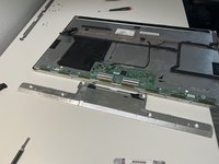
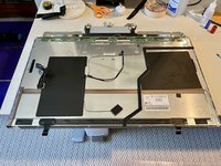
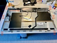
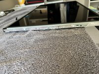
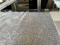
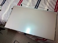
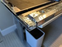
Here are the sandwiched layers of the LCD assembly along the 2 sides of the LCD assembly. It is quite involved and difficult. Consider wearing gloves to continue or if dislike gloves (sweaty) as there are many steps remaining. Need to clean LCD later with proper solution.
-
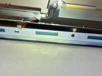
LED driver wires and brown fabric tape are only present on small sections of the sides
-
-
-
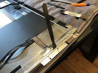
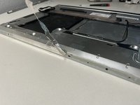
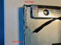
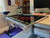
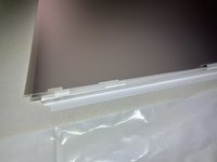
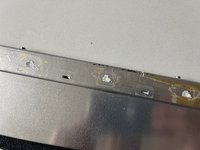
Remove 2 L shaped side brackets and 1 bottom bracket. Each bracket is held in by 4x T10. 2 side L bracket have sticky surfaces on the inside making it very difficult to pry off (use very thin metal spudger). Sticky surface is against the thin foil tape so it may scrape off some tape (its okay, need to peel it off anyways)
-
Note the picture shown with brackets removed has the foil tape already removed
-
Utility knife is better. See next step on iMac for reference.
-
-
-
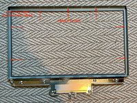
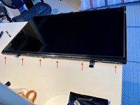
iMacs have 2 brackets. Most sticky portion are in red arrows. Use utility knife starting from less sticky to sticker portion with gradual sawing motion.
-
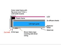
Consult previous diagram to make sure cutting between the bracket and next metal frame. Not between metal frame and interior plastic frame.
-
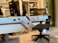
Cutting bracket this way allows them to come out straight and not bent. Easier to put back together later.
-
-
-
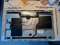
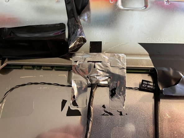
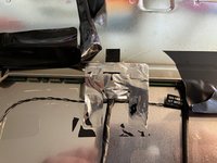
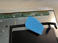
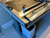
Peel off black tape surrounding the cover. Careful around the 3 connector regions (notes below) Peel off foil tape at the 2 ends of cover. Remove 4x phillips screws.
-
LCD connector is very difficult. Its a flip latch connector with a handle tape just like the other end of cable. The handle tape covered under 2 differnet sticky tapes.
-
First peel off the black tape and carefully separate the LCD connector latch handle tape.
-
Next peel off the aluminum tape and latch handle tape is finally liberated.
-
Note iMac LCD (same model as TB Display) may seal this connector area differently from Thunderbolt Display LCD.
-
-
-
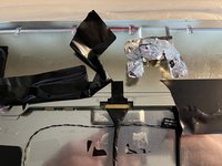
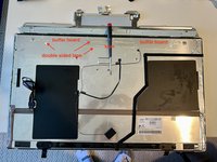
Peel off the Al tape between buffer board cover and metal frame. This allows the cover to come free without bending the clips at the hinge
-
Cover on the right side may have its edge tucked under the plastic sheet to protect against power supply board shorts. Need to lift the plastic sheet slightly to free the buffer board cover
-
Remaining steps will shown cover board flipped rather than removed. This removal step is an update for an improved procedure. Assume buffer board cover is removed in future steps.
-
-
-
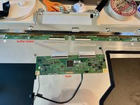
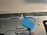
Rotate up T-Con (pivot on flex cable side) and release it from sticky tape. Likely difficult first time to release the tape.
-
Unlatch t-con to buffer board flex on buffer board side. Wiggle t-con board gently to release flex from connector (likely difficult on first release)
-
-
-
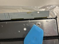
Flip up buffer board to release from sticky tape. Each side has 2 sticking points. Difficult first time to release the tape. Be gentle to avoid damaging the gold foil flex bonded between buffer board and LCD. Unrepairable without pro equipment if this foil flex bond is broken
-
Use a plastic wedge to gently cut/pry up the 2x double sided tape on both boards.
-
-
-
Takes awhile to peel off all the foil tape (where it says new foil tape in pic) on both sides.
-
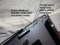
If you are a risk taker, can use an xacto knife to cut between outer metal frame and plastic frame. When near the brown tape region, careful not to cut it and the LED wires underneath.
-
-
-
-
Can use a razor blade to help remove tape along the sides. Avoid razor blade near the brown fabric tape region (has LED wires underneath) Fortunately, Al foil comes off pretty easy when over the brown fabric tape.
-
Lift up foam tape in a couple of places to peel off foil tape underneath.
-
-
-
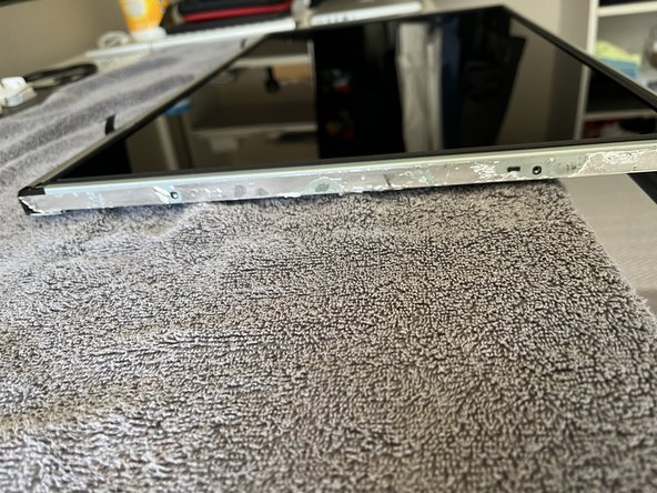
Note when outer metal frame is off, LCD will fall out if assembly is turned over so be very careful.
-
Peel back 2 black lifting tabs
-
Peel off the black tape on all 4 corners.
-
For first timer, probably best to sit LCD assembly on top of a box so the buffer boards and cover can dangle free while inserting a pry tool along the perimeter to unclip the outer metal frame. Box allows easy LCD rotation while working to unclip the 3 sides (2 sides and lifting tab side)
-
-
-
Start lifting the outer metal frame from the side with lifting tab. This is to avoid any scraping motion over the buffer board gold foil flex cable.
-
The corners on the lift tab side is slightly flexable. Probably need 2 pry tool on each side of the corner to release it. Be gentle as LCD glass is just under the outer metal frame. Luckily it sits in a plastic tub (see next steps pics) so should be safe from any prying tool
-
-
-
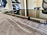
Best to just temporarily remove the small brown fabric tape on side of the LCD (They always in the way and get caught in the wrong place during reassembly) and the LCD the completely freed for removal
-
Prepare clean plastic liner on a flat surface. Suction cup lift LCD off (2 corners away from buffer boards first) and place LCD with its diffuser facing side onto the liner with buffer boards dangling over the edge. Avoid using anything with lint as a liner. The underside of the LCD facing diffusers require full disassembly to clean out any lint.
-
Remove the suction cups. Leaving suction cups on for long periods can leave a visible mark on the LCD when powered on (eventually heals but don't take a chance)
-
Always keep the LCD surface facing the diffusers downwards to avoid collecting any airborne dust.
-
-
-
Remove 6x Phillips screws on lift tab side of the plastic frame
-
Pry and unclip the plastic frame from their clip points around the perimeter.
-
-
-
Prepare clean lint free liner to cover diffuser stack after removal. I use thin garbage can liner.
-
IMPORTANT : Any crimp/fold/damage to these sheets will show up on display so handle with care. Avoid any finger print on the diffuser sheet. It is okay to handle from bottom of the white reflector sheet thats facing the tub
-
I removal the whole stack (3x diffuser sheet, plexi glass like lightguide and the white reflect sheet on the bottom) I recall there are corners near the LED bar that can lift the whole stack (will confirm in future)
-
Put stack down with white reflector sheet on the bottom on a clean surface. Cover top diffuser sheet with lint free liner.
-
-
-
Do not remove the curved LED silver reflector bar (it is brittle and difficult) There is no need
-
Do not remove the LED bar. There are thermal transfer tape underneath that will be torn up. Not necessary
-
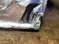
Cover connector region with Al foil to protect against heat. Wick off old lead free solder. Reflow with fresh leaded solder.
-
-
-
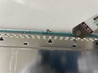
Some LED failures will show with dark spots on the bottom edge. But maybe difficult as backlight will shutoff quickly with increased brightness making it harder to see. LED tester can reveal failed LEDs after LED bar is removed.
-
Note each LED has a fragile yellow dome that converts blue light to white. These are easy to knock off. Take caution when removing the LED bar and white reflector bar.
-
The plastic reflector bar just above LEDs are very brittle. Peeling back the black tape. Sometimes an additional ultra sticky semi-transparent layer is below break all the T shaped bars on removal. Use Xacto knight to carefully cut the tape around the tabs to avoid breaking. Use hot glue help secure broken bars during reassembly.
-
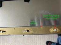
Working the reflector bar is a little tricky, Remove the 2 screws on both ends. Push and unclip all the snaps and gently slide all T bars evenly to the opening to remove. 2 ends with connector is a little tricky getting out and back in.
-
Gently pull out the connector and use a fine flat blade and magnifying eye wear to release the LED connector.
-
-
-
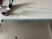
Loosen all screws and gently separate LED bar from the green heat transfer tape to avoid ripping it and keep it sticky to the tub.
-
Replace LED bar
-
If white plastic reflector bar breaks (very easily). Use tape on the backside to keep it stable during reassembly.
-
If white plastic reflector has broken T bars. Use hot glue to keep bar installed firmly against the tub during reassembly
-
-
-
If have LED tester, can test LED bar serial circuit
-
Want to see stable voltage reading. Failing LED serial circuit will show variable voltage reading. Failed LED will show lower voltage reading.
-
Note the pictured test points do not test from the connector. Connector has each series + - adjacent to each other and difficult to probe.
-
It is assume 6 pin of the LED connector is reflowed with fresh leaded solder to ensure longevity
-
-
-
Some LED bar screws have loosened over time and display will make random popping clicking noises. Good time to tighten and quiet them down.
-
-
-
Some displays have smudge marks on the bottom of the screen. This is due to the tape on the plexiglass lifting up presumably due to heat from the LEDs. Info here
-
-
-
Each LED has a yellow covered cap. These are very easy to knock off and produce blue instead of white light. Take great care to insert the hard plexiglass back into the tub to avoid knocking these off.
-
Tub has notches to align all the diffuser sheets. Top sheet is near the top of the notch and easily float around. Make sure aligned properly before clipping on the plastic frame.
-
Take great care to not crimp any of the diffuser sheets when reclipping on the plastic frame.
-
Make sure the brown fabric tape that will fold over edge of LCD is outside of the plastic frame
-
Install the 6x philips screws. Check prior picture for exact hole location. There are other holes for installing magnetic bracket. If use these holes, then can't install magnetic bracket later which require removing the fragile LCD again.
-
-
-
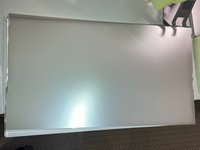
Make sure the diffuser sheet surface is clean and preferably kept clean during disassembly and no need to touch the surface. If need to clean, use mild proper cleaning solution (30% ISO, 70% distilled water mix) and micro fiber to wipe gently clean. Anything on the surface will be trapped under the LCD
-
Position everything so that the buffer board is guided over an edge and remains freely movable. Pick up the LCD with the suction cups and install it by first aligning it in the two corners opposite the buffer board. Then carefully place the LCD in the plastic frame, making sure that it is properly seated in the guides.
-
-
-
Insert the buffer board end first. Again, avoid any sliding motion over the gold buffer board to LCD flex cables.
-
Then clip in the corner opposite to the buffer board and clip in all 3 non buffer board sides.
-
Basically reverse of the motion for removal
-
LCD is now secured in the outer metal frame and the assembly can be flipped over. Make sure its on a clean flat surface when LCD is facing down. It will not touch the surface. Outer metal frame has a foam bumper around the edge. This foam bumper can easily scrape and cut when rotating LCD assembly on edge of the table so becareful.
-
-
-
Unfortunately the only way to confirm no debris, hair, thread got in between diffuser and LCD is only after LCD is installed and Display is powered up. Set a white background and inspect. So do not tape everything backup yet, may need to disassemble one more time to lift the LCD and remove the debris
-
-
-
Screw holes for the cover are alignment posts for the buffer and t-con board.
-
Insert buffer board first
-
Insert T-Con flex into buffer board connector. Lock connector tab. Set T-Con down aligned and onto the sticky tape
-
Install all 3 cables (video, temperature sensor cable and the 3rd cable) Close the cover (make sure don't crimp the temp sensor cable) Reinstall cover screws.
-
-
-
This is an important step to avoid thermally induced popping/clicking noises post assembly. The metal t-con buffer board cover is quite long, has a seam and is installed against the metal tub.
-
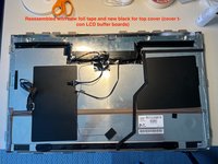
New Al foil tape over the 2 sides, all 4 corners, and both ends of the cover. Preferably clean off all the old tape
-
-
-
Remove and install new Al foil tape over cover seam. Some iMacs have tape over the entire seam rather than 3 segments shown in this pic.
-
-
-
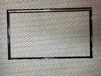
The 2 L bracket likely got bent during the difficult removal. Bend as necessary to straighten.
-
Facing LCD glass down on a flat surface. Install brackets to ensure magnets are flush against the flat surface. Install Torx Screws. This is the alignment to ensure magnetic glass installation will be flush
-
On bottom straight bracket, clamp the 2x black lifting tab under the bracket. Tabs can easily break over their folds. Not a problem.
-
-
-
While the screen is out, consider preemptively replacing the 6 or 9x 3.3Mohm resistors. Info here.
-


To reassemble your device, follow these instructions in reverse order.
To reassemble your device, follow these instructions in reverse order.
Cancel: I did not complete this guide.
One other person completed this guide.