
Battery Disconnect

Prerequisite Only
This is a prerequisite-only guide! This guide is part of another procedure and isn’t meant to be used alone.

What you need

  1. Battery Disconnect, Samsung Galaxy A51 SIM Tray Removal: step 1, image 1 of 3 Battery Disconnect, Samsung Galaxy A51 SIM Tray Removal: step 1, image 2 of 3 Battery Disconnect, Samsung Galaxy A51 SIM Tray Removal: step 1, image 3 of 3
    • Insert a SIM card eject tool, a SIM eject bit or a straightened paper clip into the hole on the SIM tray located at the left side of the phone.

    • Press firmly to eject the tray.

    • Remove the SIM card tray.

    • When reinserting the cards, make sure to properly orient them in the tray.

  2. Battery Disconnect, Back Cover: step 2, image 1 of 1
    • Before beginning this procedure, completely power off your phone.

    • Prepare an iOpener and apply it to the back cover to soften the adhesive.

    • The adhesive of the Samsung Galaxy A51 is very strong. You can use a hair dryer or a heat gun if you aren't able to open the device with the iOpener.

    • Be careful not to overheat the phone—the AMOLED display and internal battery are both susceptible to heat damage.

  3. Battery Disconnect: step 3, image 1 of 3 Battery Disconnect: step 3, image 2 of 3 Battery Disconnect: step 3, image 3 of 3
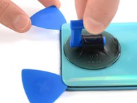
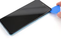
    • Insert the tip of an opening pick between the frame and the back cover at the bottom of the phone near the USB-C port.

    • If you can't get between the back cover and midframe with your opening pick, you can use a suction handle or strong tape to pull up the back cover to create a gap.

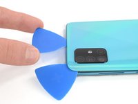
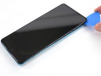
    • Slide the opening pick to the bottom right corner and leave it there.

  4. Battery Disconnect: step 4, image 1 of 3 Battery Disconnect: step 4, image 2 of 3 Battery Disconnect: step 4, image 3 of 3
    • Insert a second opening pick and slide it from the bottom right corner to the bottom left corner to cut the adhesive.

    • Leave the opening picks in place to prevent the adhesive from resealing.

  5. Battery Disconnect: step 5, image 1 of 3 Battery Disconnect: step 5, image 2 of 3 Battery Disconnect: step 5, image 3 of 3
    • Insert a third opening pick under the bottom left corner of the back cover.

    • If you have any trouble, apply more heat to further soften the adhesive. Follow the iOpener instructions to avoid overheating.

    • Slide the opening pick along the left edge of the phone.

    • Leave the opening pick in the top left corner to prevent the adhesive from resealing.

  6. Battery Disconnect: step 6, image 1 of 3 Battery Disconnect: step 6, image 2 of 3 Battery Disconnect: step 6, image 3 of 3
    • Insert a fourth opening pick under the top left corner of the back cover near the camera.

    • Slide the tip of the opening pick along the top edge of the phone to the right corner to cut the adhesive.

    • Leave the opening pick in the top right corner to prevent the adhesive from resealing.

  7. Battery Disconnect: step 7, image 1 of 3 Battery Disconnect: step 7, image 2 of 3 Battery Disconnect: step 7, image 3 of 3
    • With opening picks in all four corners, insert a fifth and final opening pick under the top right corner of the back cover.

    • Slide the tip of the opening pick along the right edge of the phone to the bottom right corner to cut the remaining adhesive.

  8. Battery Disconnect: step 8, image 1 of 1
    • Remove the back cover.

    • After installing the back cover, apply strong, steady pressure to your phone for several minutes to help the adhesive form a good bond—a stack of heavy books works well.

  9. Battery Disconnect, Midframe: step 9, image 1 of 1
    • Remove the thirteen 3 mm Phillips #00 screws securing the midframe.

  10. Battery Disconnect: step 10, image 1 of 3 Battery Disconnect: step 10, image 2 of 3 Battery Disconnect: step 10, image 3 of 3
    • The midframe is held in place by plastic clips.

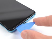
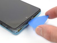
    • Insert an opening pick between the midframe and front panel assembly on the bottom of the phone near the charge port.

    • Slide the opening pick to the left bottom corner to release the plastic clips.

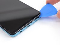
    • Slide the opening pick to the bottom right corner to release the rest of the bottom plastic clips.

  11. Battery Disconnect: step 11, image 1 of 3 Battery Disconnect: step 11, image 2 of 3 Battery Disconnect: step 11, image 3 of 3
    • Continue sliding the opening pick on the right side of your phone until all plastic clips on the right side are released.

  12. Battery Disconnect: step 12, image 1 of 3 Battery Disconnect: step 12, image 2 of 3 Battery Disconnect: step 12, image 3 of 3
    • Slide the opening pick along the top edge to release the top plastic clips.

  13. Battery Disconnect: step 13, image 1 of 3 Battery Disconnect: step 13, image 2 of 3 Battery Disconnect: step 13, image 3 of 3
    • Slide the opening pick from the top left corner to the bottom left corner to release the left side's plastic clips.

  14. Battery Disconnect: step 14, image 1 of 1
    • Remove the midframe.

  15. Battery Disconnect, Battery Disconnect: step 15, image 1 of 2 Battery Disconnect, Battery Disconnect: step 15, image 2 of 2
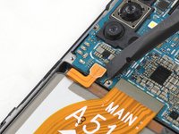
    • Use the flat end of a spudger to disconnect the battery by prying the connector straight up from its socket.

Conclusion

To reassemble your device, follow these instructions in reverse order.

Adriana Zwink

Member since: 12/18/19

62,581 Reputation

167 Guides authored

Team

iFixit Member of iFixit

Staff

123 Members

23,788 Guides authored

0 Guide Comments

Add Comment

View Statistics:

Past 24 Hours: 0

Past 7 Days: 1

Past 30 Days: 1

All Time: 98