Introduction
You can get spare parts directly from Bosch : https://www.boschtoolservice.com/de/de/b...
The error with the speed control seems to occur frequently with this machine. Unfortunately, the circuit board is potted. So only the complete circuit board can be replaced for about 37, - euros. But to do so without much prior knowledge.
What you need
-
-
To access the inner workings, first turn the 4 slotted screws from the top.
-
Then turn the 6 Philips screws from the right-hand side.
-
Attention! The 7th and last screw to be opened is located inside and holds the housing to the motor. To do this, also loosen the screw from the right using a very long or very short screwdriver or a ratchet.
-
-
-
-
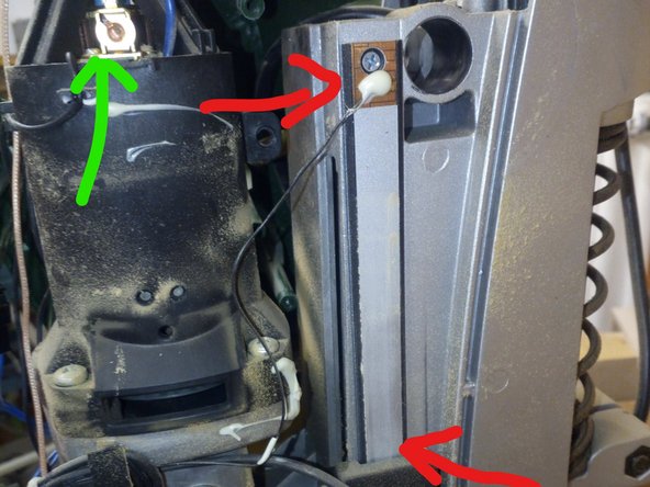
Now the front cover and the left fairing can be removed. Attention, the cables are tightly routed. Two retaining plates (red arrows) for the cables must be loosened to work better. Behind the speed controller is a loose adapter to the circuit board ... do not lose it.
-
All cables from the board to be replaced (orange rectangle) can be disconnected inside the unit. There is no need for soldering or clamping.
-
To get to one of the black cables, the right side of the housing must also be removed. To do this, open the screw for the axis of the height adjustment and pull out the axis. ATTENTION: Hold the gear wheel in the middle and watch out for the small elongated driver.
-
-
-
On the right side there is also an adapter from the transmission switch to the transmission. This is only plugged on and tricky to assemble.
-
Now you could also change the carbon brushes (green arrow). The red arrow shows the measuring bar
-
From below the drill head, you can see the round magnet and the sensor board for the RPM measurement. By the way, the speed is only displayed, but has no control function. This is only done by the speed controller in analog mode.
-


Work through the steps in reverse order to reassemble your device.
Work through the steps in reverse order to reassemble your device.
Special thanks to these translators:
100%

oldturkey03 is helping us fix the world! Want to contribute?
Start translating ›

Team

erfindergarden foundation Member of erfindergarden foundation
Local Repair Groups
5 Members
42 Guides authored
9 Comments
Leider ist die benötigte Platine bei Bosch nicht mehr lieferbar, insofern bleibt nur noch der Kauf einer gebrauchten Platine. Oder gibt es hier evtl. einen alternativen Anbieter?
Z. B. Hier: https://www.ersatzteileonline.de/bosch/p... oder vielleicht auch woanders Teilen. 811/2
Hi thanks for the guide on how to replace this circuit board. I did manage to buy a new circuit board directly via Bosch. Sadly this has not resolved the issue: video of after installing a new circuit board: https://www.youtube.com/shorts/cCa8lGZz0...
Had you replaced the Power Board Nr. 811/2 or 811/1?
Hi Andreas, sorry i only read your comment today. I replaced the circuit board 804/9
part number: 1600A000TH
Do you think i should have replaced the powerboard 811/2 and 811/1 ? I am quite sure that these parts are working well.