Introduction
This guide will show how to get to and replace the motherboard.
What you need
-
-
Remove two 6.8 mm JIS #000 screws on the right side.
-
Remove six 5.3 mm JIS #000 screws on the bottom.
-
Remove two 5.3 mm JIS #000 screws on either side of the viewfinder.
-
-
-
-
Remove the five ribbon connectors along the bottom of the assembly using either needle nose tweezers or a plastic opening tool to flip the small flaps to the "up" position.
-
Use a nylon spudger to pull each ribbon connector out of its connection using the hole in the center of the ribbon.
-
-
-
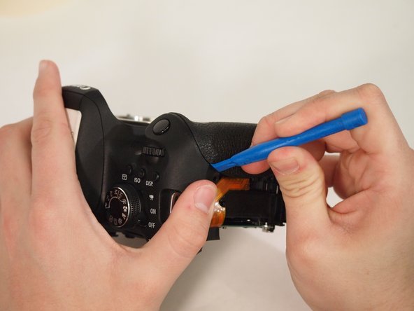
Remove the yellow and red connections on the front near the black cylinder (capacitor).
-
The yellow connector will just pop out if pried from the bottom using a plastic opening tool.
-
The red connector will pull out of the casing with either a plastic opening tool or a thin set of tweezers.
-
-
-
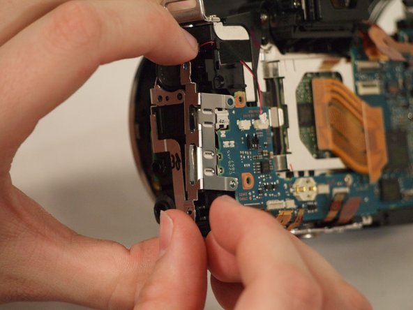
Disconnect the ribbon connector on the upper right side of the motherboard.
-
Pull back the foam on the connector on the far right side of the motherboard.
-
Flip up the tab on the connector and remove the cable.
-


To reassemble your device, follow these instructions in reverse order.
To reassemble your device, follow these instructions in reverse order.
Cancel: I did not complete this guide.
7 other people completed this guide.
Team

University of Memphis, Team S2-G1, Kim Spring 2018 Member of University of Memphis, Team S2-G1, Kim Spring 2018
UM-KIM-S18S2G1
3 Members
11 Guides authored
2 Comments
Good tutorial! Two things I noticed on my teardown, on step 6 the white grounding wire has two black tabs on either side you can lift with a guitar pick, much better than pulling on the wire casing; on step 12 the picture is misleading as you pull the plug out towards the middle of the body. Those are very minor things, this was an extremely helpful tutorial! Not for the faint of heart aha