Introduction
Having suspicion that your handset is not charging well due to bad contact? You've come to the right guide!
What you need
-
-
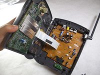
Turn the base over. You will see four 11mm Phillips #0 screws, one in each corner.
-
Use a screwdriver to remove all four 11mm Phillips #0 screws.
-
-
-
-
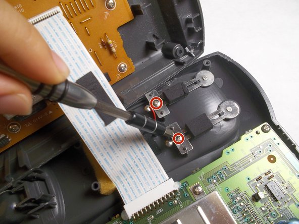
Locate the charging component towards the bottom of the grey, plastic, phone-shaped extrusion. It is composed of two metal pieces; each is fastened by a 5mm Phillips #0 screw.
-
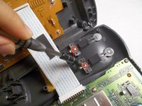
Remove both 5mm Phillips #0 screws to release the metal pieces.
-
-
-
Cut the black and red wires to finish removal, and then solder your new replacement component.
-
For more help on soldering, please refer to the iFixit Solder and Desolder Guide.
-


To reassemble your device, follow these instructions in reverse order.
Cancel: I did not complete this guide.
2 other people completed this guide.
Team

IUPUI, Team 3-3, Harley Fall 2016 Member of IUPUI, Team 3-3, Harley Fall 2016
IUPUI-HARLEY-F16S3G3
4 Members
17 Guides authored