
Flash Motherboard
Introduction
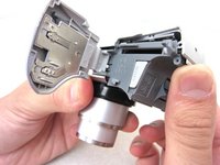
Go to step 1If your flash settings are set correctly but your camera does not flash, you will need to replace the flash motherboard. First, you will need to remove the front and back covers. Once that is complete, you will have access to the flash motherboard.
What you need


-
-
Unscrew a total of 6 4.45 mm phillips head screws using a #00 phillips head screwdriver.
-
There are 2 screws on the left side (when looking at the front of the camera).
-
There are 3 screws on the bottom
-
There is 1 screw on the right side
-
-
-
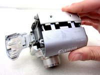
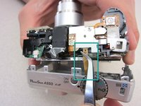
Turn to the front of the camera.
-
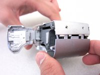
Find the flash motherboard located behind the flash assembly on the top right.
-


To reassemble your device, follow these instructions in reverse order.
To reassemble your device, follow these instructions in reverse order.
Cancel: I did not complete this guide.
4 other people completed this guide.
Team

Cal Poly, Team 8-6, Regan Spring 2011 Member of Cal Poly, Team 8-6, Regan Spring 2011
CPSU-REGAN-S11S8G6
4 Members
22 Guides authored