
HP Windows Mixed Reality Controllers TPC-Q044 Main Circuit Board Replacement
Introduction
Go to step 1This guide goes over how to replace the controller's main circuit board.
If your TPC-Q044 circuit board starts failing when using your controller, you may want to think about replacing the component. The failure may be a result of bad soldering or missed connections. The replacement of the circuit board is not too complex. A couple of screwdrivers and a spudger will be sufficient to complete this task. There are no warnings or potential hazards when replacing the board.
What you need


-
-
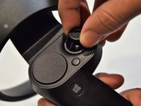
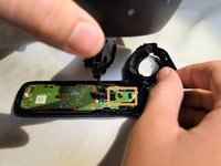
Grip the main body and pull the joystick outwards until the entire front panel pops off.
-
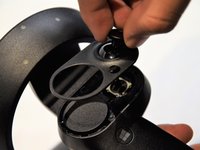
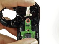
Remove the 6mm screw in the corner of the joystick well using a Phillips #00 screwdriver.
-
-
-
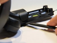
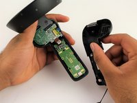
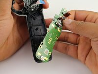
Use a spudger to pry apart the two halves of the assembly.
-
Work slowly, prying a small section at a time until the halves are completely separated.
-
-
-
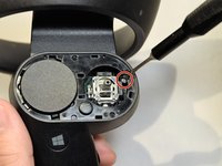
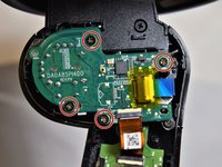
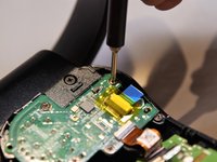
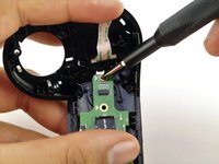
Using a Phillips #00 screwdriver, remove the four 4mm screws located on the joystick circuit board underneath the top half of the controller.
-
-
-
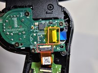
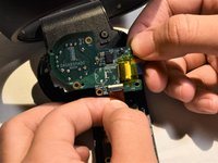
Remove the orange flat cable by pulling the orange tab parallel to the circuit board.
-
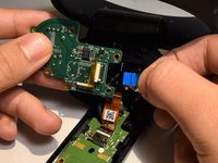
Release the blue flat cable by lifting up the white latch with a spudger.
-
-
-
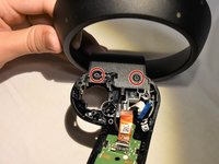
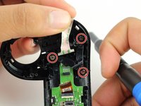
Remove the two 6mm screws at the base of the ring using a Phillips #0 screwdriver.
-
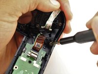
Pull towards the base of the controller to release the black wire from the connector on the circuit board.
-
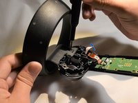
Pull the ring apart from the rest of the controller.
-
-
-
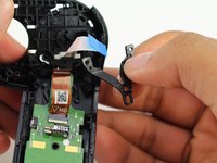
Remove the two 3mm screws on the V-clip using a Phillips #00 screwdriver.
-
Remove the V-clip from the device.
-
-
-
With the V-clip off of the controller, use a Phillips #00 screwdriver to remove the remaining 4mm screw.
-
Remove the circuit board.
-


Team

Cal Poly, Team S1-G2, Maness Spring 2019 Member of Cal Poly, Team S1-G2, Maness Spring 2019
CPSU-MANESS-S19S1G2
4 Members
7 Guides authored