Introduction
Use this guide to replace the I/O board.
What you need
-
Tool used on this step:Magnetic Project Mat$19.95
-
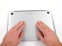
Remove the following ten screws securing the lower case to the upper case:
-
Two 2.3 mm P5 Pentalobe screws
-
Eight 3.0 mm P5 Pentalobe screws
-
-
Tool used on this step:Tweezers$4.99
-
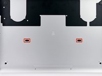
Grasp the Interposer with tweezers.
-
Lift the Interposer off the logic board and remove it.
-
-
-
-
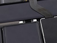
Remove the following screws securing the heat sink to the logic board assembly:
-
One 2.4 mm Phillips #00 screw
-
One 3.4 mm T5 Torx screw
-
Four 2.7 mm T5 Torx screws
-
-
-
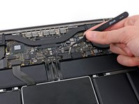
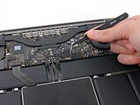
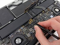
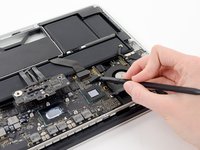
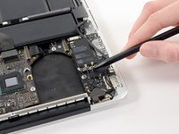
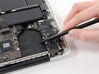
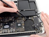
Use the flat end of a spudger to pry the right side of the I/O board data cable connector up off its socket on the I/O board.
-
-
-
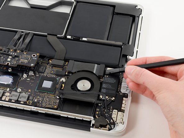
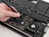
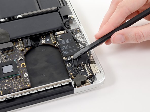
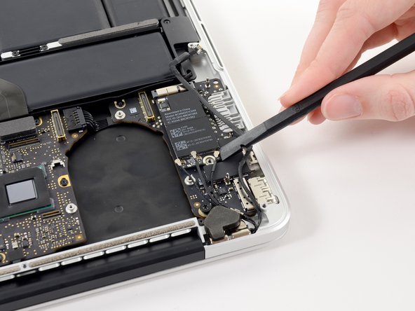
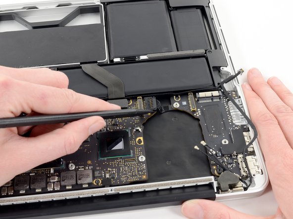
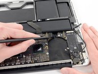
Use the tip of a spudger to flip up the retaining flap on the right fan ribbon cable ZIF socket.
-
Pull the right fan ribbon cable straight out of its socket on the logic board.
-
-
-
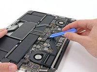
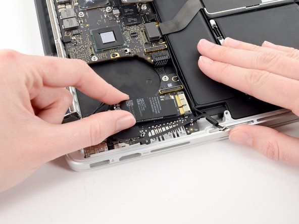
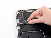
Remove the single 2.7 mm T5 Torx screw securing the AirPort board to the I/O board.
-
-
-
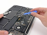
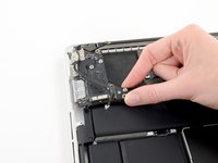
Use the flat end of a spudger to pry and disconnect the three antenna cable connectors from the AirPort board.
-
Connect the long-sleeved cable to the center socket.
-
The short-sleeved cable connects next to the screw.
-
The remaining cable has no sleeve, and connects in the last empty socket, next to the fan.
-
-
-
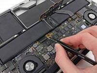
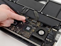
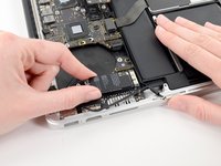
Use the tip of a spudger to push the edges of the I/O board power connector straight out of its socket on the logic board.
-


To reassemble your device, follow these instructions in reverse order.
To reassemble your device, follow these instructions in reverse order.
Cancel: I did not complete this guide.
2 other people completed this guide.

