Introduction
Follow these instructions to replace the glued-in battery in your MacBook Pro using an iFixit kit with adhesive remover. The adhesive remover helps weaken the glue securing the old battery, making it easier to remove.
iFixit adhesive remover is flammable. Follow this procedure in a well-ventilated area, and don’t smoke or work near an open flame.
To minimize risk of damage, turn on your MacBook and allow the battery to fully discharge before starting this procedure. If a charged lithium-ion battery is accidentally punctured, a dangerous and uncontrollable fire may result. If your battery looks puffy or swollen, take extra precautions.
Note: The solvent used to dissolve the battery adhesive can damage certain plastics. Follow all instructions and take care where you apply the adhesive remover.
What you need
-
-
Power on your Mac and launch Terminal.
-
Copy and paste the following command (or type it exactly) into Terminal:
-
sudo nvram AutoBoot=%00
-
Press [return]. If prompted, enter your administrator password and press [return] again. Note: Your return key may also be labeled ⏎ or "enter."
-
sudo nvram AutoBoot=%03
-
-
Tool used on this step:Magnetic Project Mat$19.95
-
Use a P5 Pentalobe driver to remove the six screws securing the lower case:
-
Two 6.2 mm screws
-
Four 3.4 mm screws
-
-
-
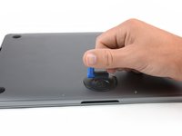
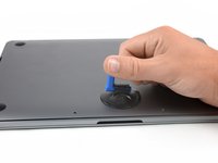
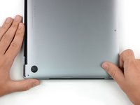
Apply a suction handle to the lower case near the front-center area of the MacBook Pro.
-
Lift the suction handle to create a slight gap between the lower case and the chassis.
-
-
-
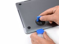
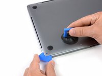
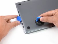
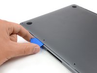
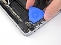
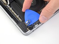
Insert one corner of an opening pick into the space between the lower case and the chassis.
-
Slide the opening pick around the nearest corner and halfway up the side of the case.
-
-
-
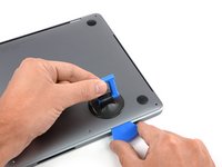
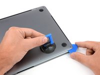
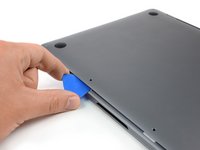
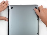
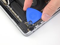
Insert your opening pick once again under the front edge of the lower case, near one of the two centermost screw holes.
-
Give the pick a firm twist to pop free the third clip securing the lower case to the chassis.
-
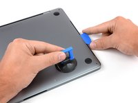
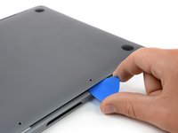
Repeat this procedure near the other of the two centermost screw holes, popping the fourth clip free.
-
-
-
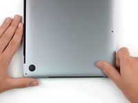
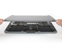
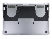
Remove the lower case.
-
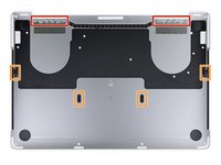
Set it in place and align the sliding clips near the display hinge. Press down and slide the cover toward the hinge. It should stop sliding as the clips engage.
-
When the sliding clips are fully engaged and the lower case looks correctly aligned, press down firmly on the lower case to engage the four hidden clips underneath. You should feel and hear them snap into place.
-
-
-
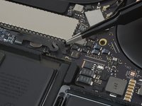
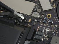
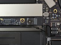
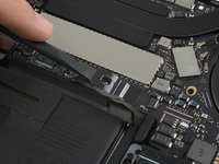
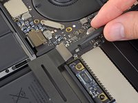
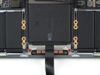
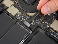
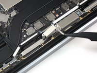
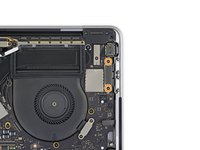
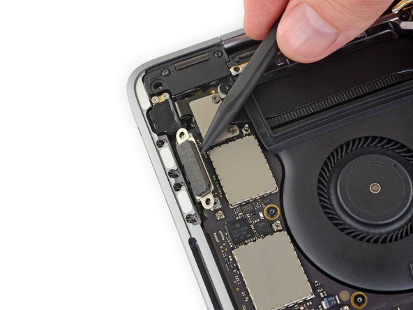
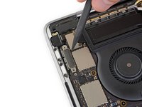
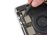
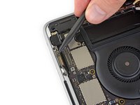
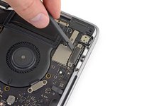
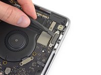
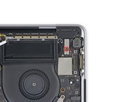
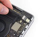
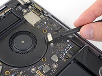
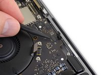
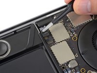
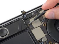
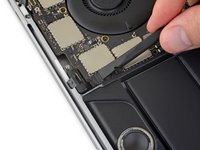
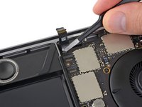
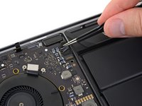
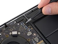
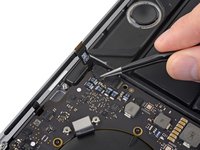
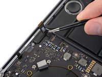
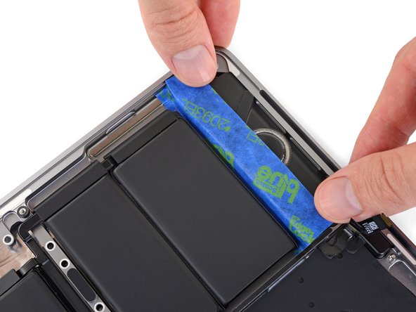
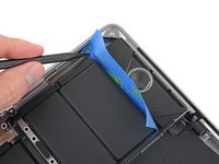
Carefully peel up the large piece of tape covering the battery connector, on the edge of the logic board nearest the battery.
-
Remove the tape.
-
-
-
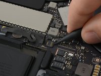
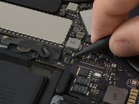
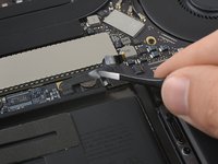
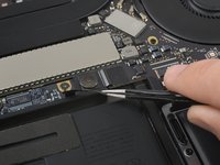
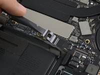
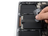
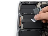
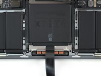
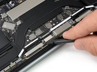
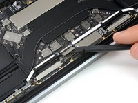
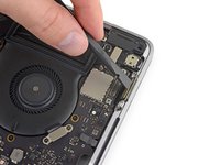
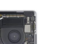
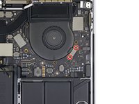
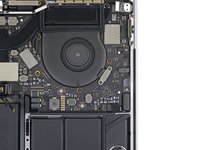
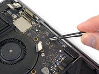
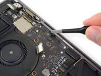
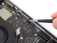
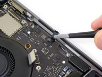
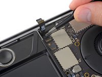
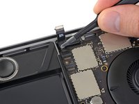
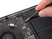
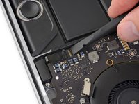
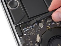
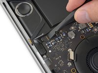
Use a spudger to gently lift the battery power connector, disconnecting the battery.
-
Lift the connector high enough so that it stays separated from its socket. If it accidentally makes contact during the course of your repair, it could damage your MacBook Pro.
-
-
-
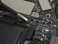
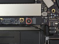
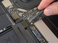
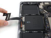
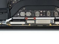
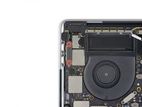
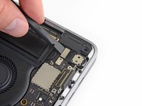
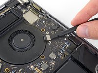
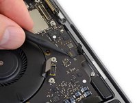
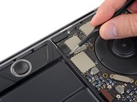
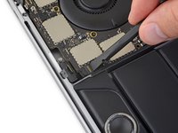
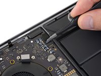
Use a T3 Torx driver to remove the two 1.8 mm screws securing the trackpad cable connector bracket.
-
-
-
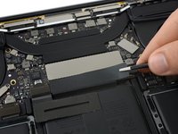
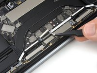
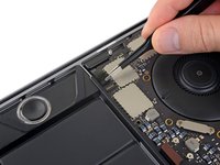
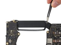
Use a spudger to disconnect the trackpad ribbon cable by gently prying its connector straight up from the logic board.
-
-
-
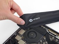
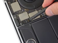
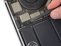
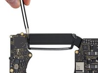
Prepare an iOpener and lay it on top of the trackpad ribbon cable for about a minute, in order to soften the adhesive securing the trackpad ribbon cable to the top of the battery.
-
If you don't have an iOpener, use a hair dryer to warm up the cable instead. The cable should be warm, but not too hot to touch. Be careful not to overheat the battery.
-
-
-
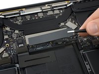
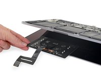
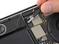
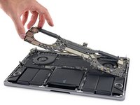
Carefully peel the trackpad ribbon cable up off the battery, and push it out of the way.
-
-
-
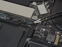
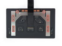
Use a T5 Torx driver to remove the ten screws securing the trackpad assembly:
-
Two 4.3 mm screws
-
Eight 5.8 mm screws
-
-
-
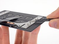
Remove the trackpad assembly.
-
Be sure not to lose the six small washers (two circular and four rectangular) resting on the underside of the trackpad.
-
-
-
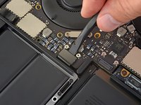
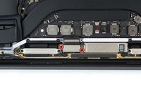
Use a T3 Torx driver to remove the two 1.9 mm screws from the keyboard connector bracket.
-
-
-
Use a spudger to disconnect the keyboard connector by prying it straight up from the logic board.
-
-
-
Remove the two 2.9 mm T3 Torx screws securing the aluminum cover on top of the main display cable.
-
Remove the cover.
-
-
-
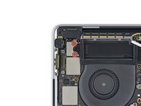
Using a T3 Torx driver:
-
Remove two 1.4 mm screws from the Thunderbolt port connector bracket on the left.
-
Remove two more 1.4 mm screws from the Thunderbolt port connector bracket on the right.
-
-
-
-
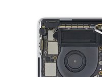
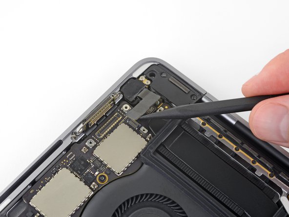
Use a spudger to disconnect the left-side Thunderbolt port connector by prying it straight up from the logic board.
-
Gently push the connector aside so it won't interfere with logic board removal.
-
-
-
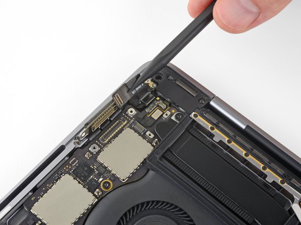
Repeat for the right-side Thunderbolt port connector, prying it up from the inside edge and pushing it carefully aside.
-
-
-
Use a T3 Torx driver to remove the two 1.9 mm screws from the cover bracket securing the Touch ID and 3.5 mm audio jack connectors.
-
-
-
Use a spudger to disconnect the 3.5 mm audio jack flex cable by prying it straight up from the logic board.
-
Gently push the flex cable aside.
-
-
-
Disconnect the Touch ID and power button flex cable by prying it straight up from the logic board.
-
-
-
Apply mild heat using an iOpener, heat gun, or hair dryer to soften the adhesive under the power button/Touch ID flex cable.
-
-
-
Carefully slide an opening pick under the flex cable to separate it from the logic board, and push it carefully aside.
-
If you have trouble, don't force it—apply a little more heat and try again.
-
-
-
Use a T3 Torx driver to remove the 1.9 mm screw from the Touch Bar digitizer connector bracket.
-
-
-
Use a spudger to disconnect the Touch Bar digitizer by prying its connector straight up from the logic board.
-
-
-
Use a T3 Torx driver to remove two 1.9 mm screws from the Touch Bar display connector bracket.
-
-
-
Use a spudger to disconnect the Touch Bar display connector by prying it straight up from the logic board.
-
-
-
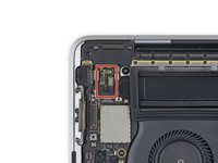
Peel back any tape covering the microphone connector socket.
-
-
-
Open the locking flap on the microphone cable's ZIF connector by prying it straight up from the logic board.
-
-
-
Flip open the locking flap for the left-side tweeter ZIF connector by prying it straight up from the logic board.
-
-
-
Flip open the locking flap for the left main speaker ZIF connector by prying it straight up from the logic board.
-
-
-
Flip open the locking flap for the right-side tweeter ZIF connector by prying it straight up from the logic board.
-
-
-
Flip open the locking flap for the right-side main speaker ZIF connector by prying it straight up from the logic board.
-
-
Tool used on this step:Tweezers$4.99
-
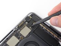
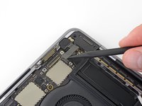
Disconnect the first antenna cable by prying it straight up from its socket.
-
Carefully slide your tweezers or the flat end of your spudger underneath the cable until it's near the socket, and then gently twist or pry up to disconnect it.
-
-
-
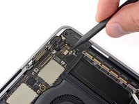
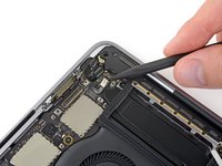
Use a T5 Torx driver to remove the 2.9 mm screw securing the antenna cable bundle.
-
-
-
Remove all ten screws securing the logic board assembly:
-
Three 2.5 mm Torx T3 screws
-
Five 2.9 mm Torx T5 screws
-
Two 3.0 mm Torx T5 screws
-
-
-
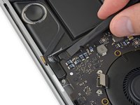
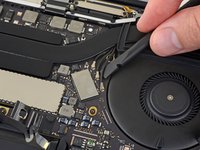
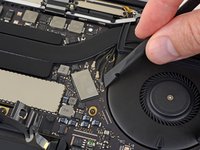
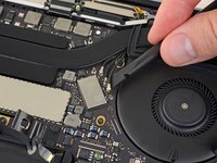
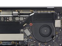
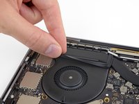
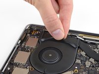
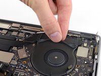
Peel up (but don't remove) the two rubber vibration damping strips from the adhesive holding them to the fans.
-
If needed, apply mild heat with an iOpener, hair dryer, or heat gun to soften the adhesive and make the dampers easier to separate.
-
-
-
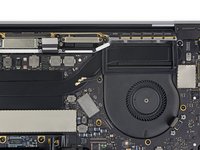
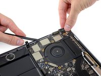
Lift from the left side to remove the logic board assembly.
-
-
-
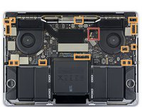
Check the alignment of the rubber vibration dampers, and adjust them as needed.
-
Feed the antenna cable bundle through the gap between the logic board and heat sink, and make sure it lines up correctly as you lower the board into place.
-
Verify that no cables get trapped under the board as you install it. Check each marked location carefully.
-
-
-
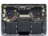
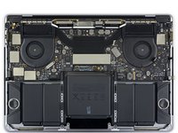
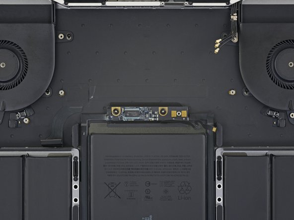
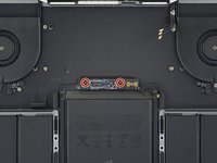
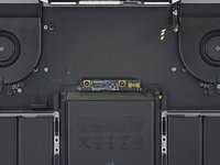
Use a T5 Torx driver to remove the two 3.2 mm screws from the battery board.
-
-
-
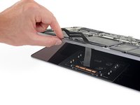
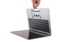
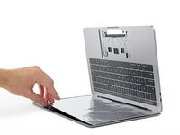
To protect your display, place a sheet of aluminum foil between the display and keyboard and leave it there while you work.
-
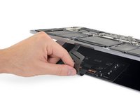
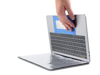
Additionally, use some tape and/or foil to seal off the area under the trackpad. Optionally, you may also layer an absorbent towel directly underneath the trackpad area to soak up any excess adhesive remover.
-
-
-
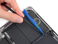
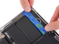
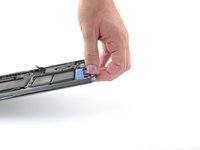
Cut a length of packing tape or painter's tape, and slide one edge between the battery and the speaker on the left side.
-
-
-
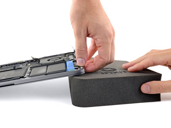
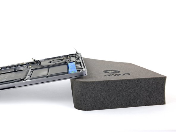
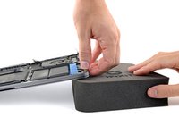
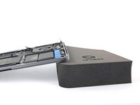
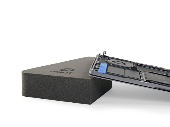
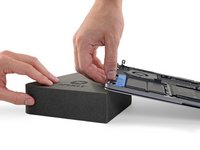
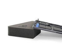
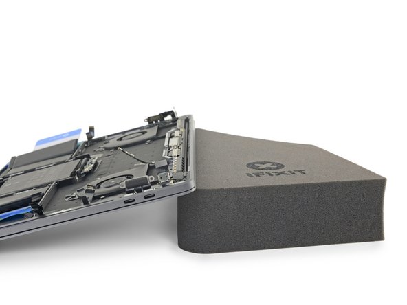
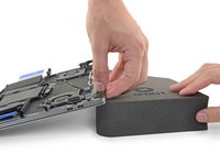
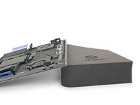
To control the flow of adhesive remover and direct it away from the speaker, raise the right edge of your MacBook Pro a few inches using a book or foam block.
-
-
-
Now that your MacBook Pro is fully prepped, it's time to prep yourself.
-
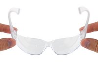
Wear eye protection when handling and applying the adhesive remover. (Eye protection is included in your kit.)
-
Do not wear contact lenses without eye protection.
-
Protective gloves are also included in your kit. If you are concerned about possible skin irritation, put your gloves on now.
-
-
-
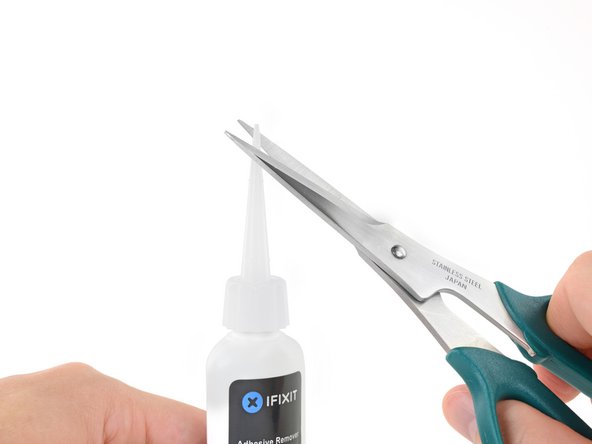
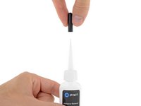
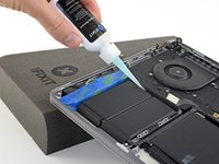
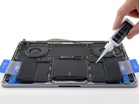
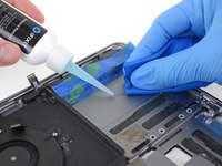
Pull off the black rubber stopper from your bottle of adhesive remover.
-
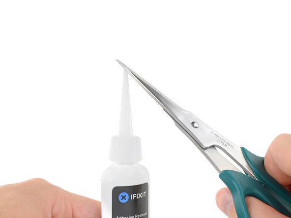
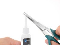
Use scissors to cut off the sealed tip of the applicator.
-
Cutting close to the narrow tip will give you better control so you can apply the adhesive remover in small amounts.
-
-
-
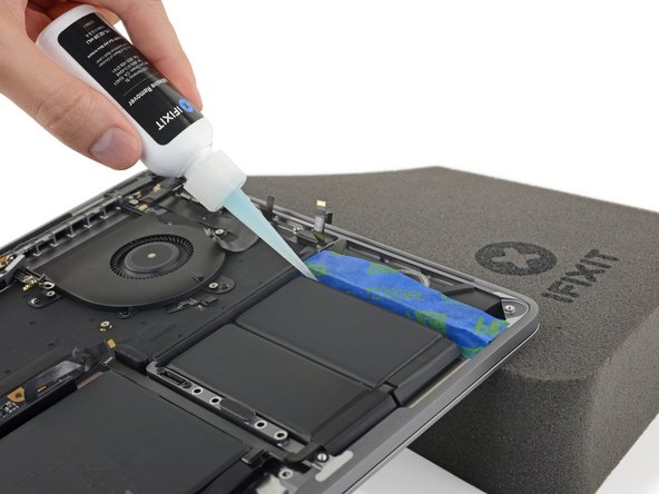
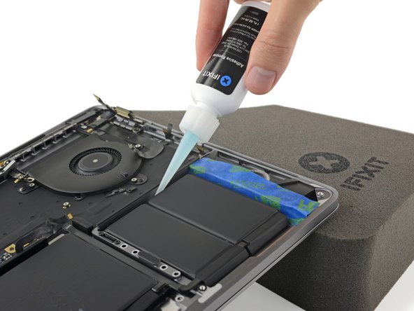
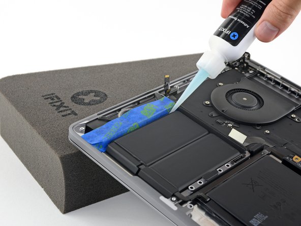
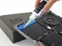
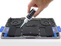
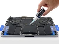
Apply a few drops of adhesive remover underneath the far right battery cell.
-
Wait about two minutes for the adhesive remover to penetrate and soften the battery adhesive before you proceed to the next step.
-
-
Tool used on this step:Plastic Cards$2.99
-
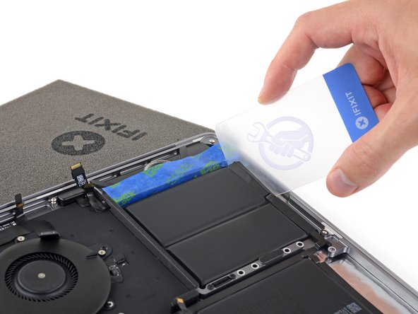
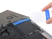
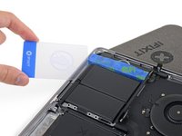
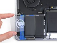
After a couple minutes, insert one corner of a plastic card underneath the far right battery cell, starting from the front edge.
-
Wiggle the card from side to side and slide it all the way under the battery cell.
-
Lift to fully separate the adhesive, but don't try to remove the battery cell yet.
-
Leave the plastic card temporarily underneath the cell to prevent it from re-adhering while you continue.
-
-
-
If you have difficulty getting the card underneath any of the battery cells, try working a piece of floss or wire underneath the battery cell. Pull it side-to-side in a sawing motion to separate the adhesive.
-
-
-
Repeat the last few steps to separate the far left battery cell.
-
Begin by elevating the left side of the MacBook Pro to direct the flow of adhesive remover away from the speaker.
-
-
-
Apply a few drops of adhesive remover under the far left battery cell, and wait about two minutes for it to penetrate.
-
-
-
Slide one corner of a plastic card underneath the far left battery cell, and carefully separate the adhesive holding it in place.
-
Leave the plastic card temporarily underneath the cell to prevent it from re-adhering while you continue.
-
-
-
Next, raise the back edge of your MacBook Pro to direct the flow of adhesive remover away from the keyboard/logic board area.
-
-
-
Apply a few drops of adhesive remover under each of the remaining three battery cells.
-
Be mindful of leaks, and apply more adhesive remover in the following steps if needed.
-
Wait about two minutes before you continue.
-
-
-
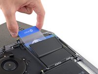
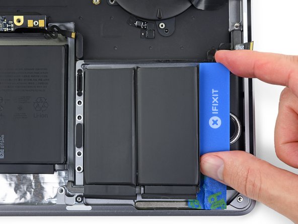
Slide a plastic card all the way underneath the far left battery cell—which you already separated in the previous steps—and then insert it carefully between the remaining left-side battery cell and the MacBook Pro's aluminum case.
-
-
-
Repeat the previous two steps to separate the remaining battery cell on the right.
-
-
-
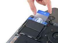
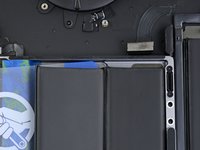
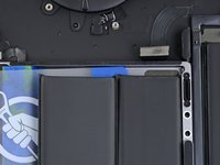
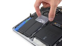
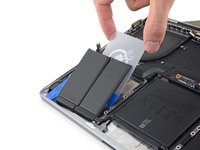
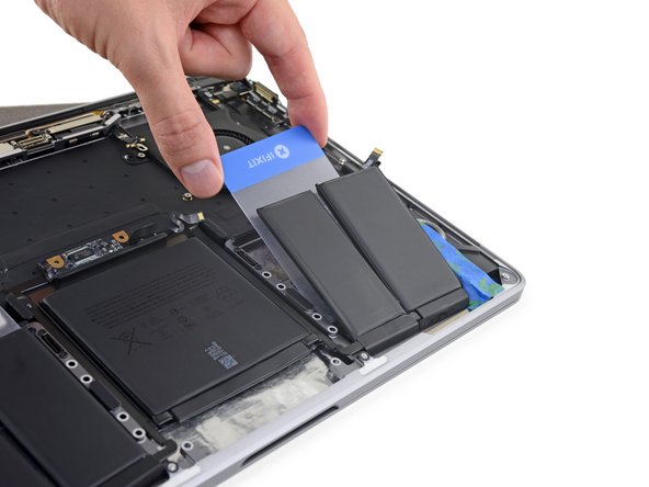
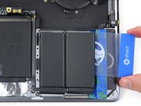
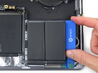
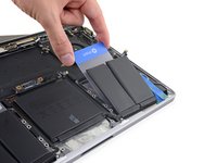
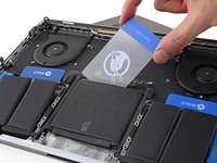
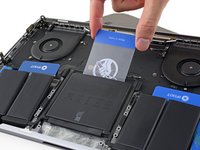
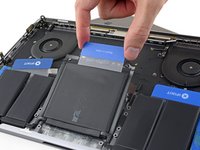
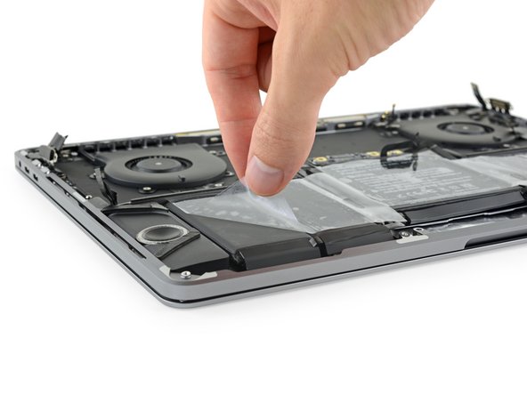
Slide the corner of one of your plastic cards underneath the top edge of the large center battery cell.
-
Wiggle the card from side to side and slide it underneath the battery cell to fully separate the adhesive holding it in place.
-
-
Tool used on this step:Tweezers$4.99
-
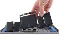
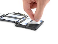
Remove the battery.
-
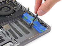
Before installing a new battery, remove all remaining adhesive from the MacBook Pro's case.
-
Peel off any large strips of adhesive using tweezers or gloved fingers.
-
Scrape away any remaining chunks of adhesive with a plastic tool, and clean the underlying areas with adhesive remover or isopropyl alcohol. Wipe in one direction (not back and forth) until the chassis is clean and ready for your new battery.
-
When you're done, carefully remove the protective tape from the speakers.
-
-
Tool used on this step:Tesa 61395 Tape$12.99
-
Be mindful of the battery data cable and make sure it doesn't get pinched or trapped under the battery board.
-
If your battery came with adhesive pre-installed on the bottom, flip it over and carefully peel away the liner to expose the adhesive. If your battery did not come with adhesive, apply a thin double-sided adhesive tape such as Tesa 61395 to keep your battery in place.
-
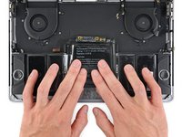
Carefully position the battery and set it into place.
-
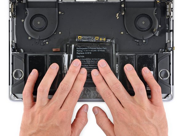
Press and hold each cell firmly for 5-10 seconds to secure it to the lower case.
-


Compare your new replacement part to the original part—you may need to transfer remaining components or remove adhesive backings from the new part before installing.
To reassemble your device, follow the above steps in reverse order.
Take your e-waste to an R2 or e-Stewards certified recycler.
Repair didn’t go as planned? Try some basic troubleshooting or search our Answers community for help.
Cancel: I did not complete this guide.
91 other people completed this guide.


43 Comments
Amazing, Thanks
does this also work for the 2018 model?
Why do you remove the logic board? There are videos on youtube that demonstrate that there is no need to remove the logic board or the trackpad to replace the battery ...
no need to remove the logic board .
Cosmin -
Just finished replacing - stopped at step 23 after removing the Track Pad. Did not have to remove Logic Board. You don’t even need to remove the Track Pad, but because of the glue on the center cell, it’s probably a good idea and a pretty easy step to keep Track Pad safe when prying the cell off the case. It does take a bit of careful “jiggling” to remove the old battery and to slide the new one under the LB, but IMO definitely much (MUCH!) easier than removing all of the components after step 23.
Vadique -