Introduction
Use this guide to replace a broken MagSafe DC-In board.
What you need
-
-
Remove the following ten screws:
-
Three 14.4 mm Phillips #00 screws
-
Three 3.5 mm Phillips #00 screws
-
Four 3.5 mm shouldered Phillips #00 screws
-
-
-
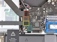
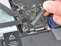
Use the edge of a spudger to pry the battery connector upwards from its socket on the logic board.
-
-
-
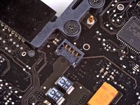
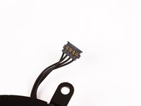
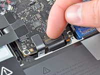
Use the edge of a spudger to gently pry the fan connector up and out of its socket on the logic board.
-
-
-
-
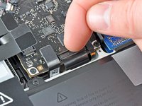
Use the tip of a spudger to pull the right speaker/subwoofer cable out from under the retaining finger molded into the upper case.
-
Pull the right speaker/subwoofer cable upward to lift the connector out of its socket on the logic board.
-
-
-
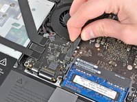
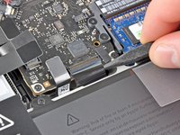
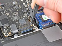
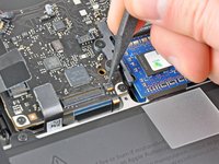
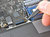
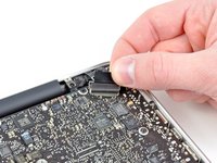
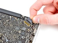
Pull the MagSafe DC-In board cable toward the heat sink to disconnect it from the logic board.
-
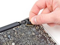
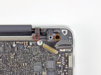
Remove the MagSafe DC-In board.
-


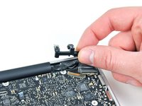


To reassemble your device, follow these instructions in reverse order.
To reassemble your device, follow these instructions in reverse order.
Cancel: I did not complete this guide.
128 other people completed this guide.

19 Comments
It's worth noting that the two ribbon cables held in place by ZIF connectors are a real pain to put back in - it's very hard to get any force pushing them back into the ZIF connector. It took two small tweezers and a bit of luck on the keyboard cable.
To get back the keyboard ribbon I put the piece of Anti-Static Kapton Tape to enter it.
As stated the keyboard connector is a nightmare to get back in, how I finally did it is, I presented the cable to the socket and using a sticky label pressing down pulled the label towards the centre of the mainboard
The magsafe connector is not under the mainboard and it would be easy for apple to have designed it so that the socket was on the top not the underside of the mainboard
I was using my Laptop (literally in my lap), with the charger connected when it felt very warm on my pant leg. Felt the bottom of the case by the Mag Safe connector and it was very hot, almost burnt my hand. Surprisingly hot. Wouldn't charge right after that, kept getting hot, intermittent charging. Looked at the contacts with a jewelers loupe; the gold contacts were burnt and blistered, plastic melted so it wouldn't make full contact with the AC charger. Charger contacts OK. Replaced DC in board, works like new, saved a bundle of cash. Laid all the screws out in related groups on table top. e.g. All 10 cover screws in a square. MoBo Screws in MoBo pattern, or, you could use a small metric/millimeter ruler to tell which screw goes where.
This is a terrific guide. My project, a mid-2009 13" MacBook Pro 5,5, was a little different, and the biggest challenges I experienced were places where my computer's connections were different than the model illustrated. So I'll share how that computer differed for those who might come up against the same challenges. I'll add those notes and illustrations in the sections that apply.
I lucked out with the two keyboard ribbon cables. I simply nudged them into place with two different spudgers—one to pry gently upward from underneath, the other to redirect that force to press the cable directly into its slot. I was anticipating a struggle, but it was a nothing.
Thanks for the great work, Andrew Bookholt, and everyone else!