Introduction
Did your laptop go for an accidental swim? Logic board fried? Use this guide to install a new logic board in your MacBook Pro 15" Retina Display Early 2013.
What you need
-
-
Remove the following P5 pentalobe screws securing the lower case to the MacBook Pro:
-
Eight 3.0 mm
-
Two 2.3 mm
-
-
Tool used on this step:Tweezers$4.99
-
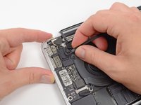
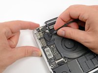
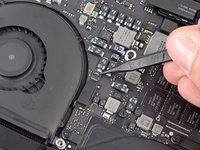
Use a spudger or tweezers to pry the three AirPort antenna cables straight up off of their sockets on the AirPort board.
-
-
-
Use the flat end of a spudger to pry the rubber hinge covers up off the left and right hinges.
-
-
-
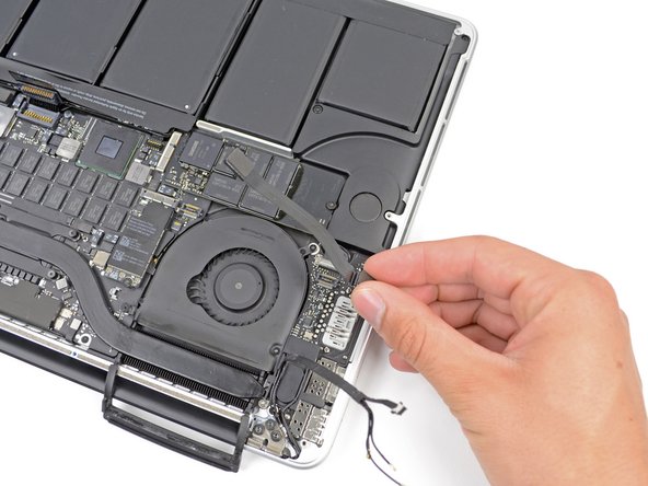
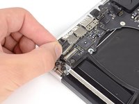
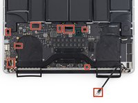
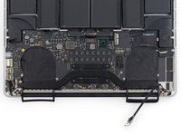
Using the flat end of a spudger, pry the I/O Board connector straight up out of its socket on the logic board.
-
In a similar fashion, remove the I/O Board cable connector from its socket on the I/O Board.
-
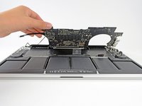
Remove the I/O Board cable from the MacBook Pro.
-
-
-
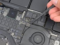
Remove the single 2.9 mm T5 Torx screw securing the AirPort card to the logic board.
-
-
-
-
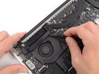
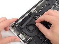
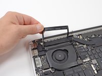
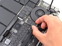
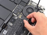
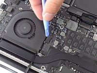
Use the flat end of a spudger to lift the rubber heat sink cover up off the left fan.
-
-
-
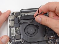
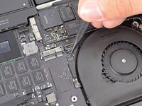
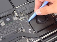
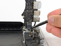
Use the tip of a spudger to flip up the I/O board data cable lock and rotate it toward the battery side of the computer.
-
Use the flat end of a spudger to slide the I/O board data cable straight out of its socket on the logic board.
-
-
-
Use the flat end of a spudger to pry the left speaker connector up and out of its socket on the logic board.
-
Use the tip of a spudger to pry the right speaker connector up and out of its socket on the logic board
-
-
-
Peel back the tape covering the top of the keyboard ribbon cable connector.
-
Use the flat end of a spudger to flip up the retaining flap on the keyboard ribbon cable ZIF socket.
-
Use the flat end of a spudger to push the keyboard ribbon cable out of its socket.
-
-
-
Remove the four 3.5 mm T5 screws securing the heat sink to the logic board.
-
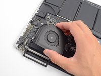
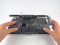
Grip both ends of the heat sink and lift it up from the logic board.
-
-
-
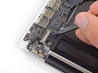
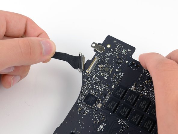
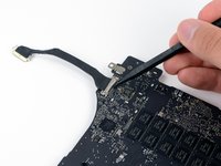
Use the tip of a spudger to flip up the metal retaining flap on the HDMI data transfer cable.
-
Gently pull the HDMI data transfer cable straight out of its socket on the logic board.
-


To reassemble your device, follow these instructions in reverse order.
To reassemble your device, follow these instructions in reverse order.
Cancel: I did not complete this guide.
45 other people completed this guide.

6 Comments
Very interesting. Thanks.
Question: is it possible to replace a Early 2013 Logic Board with a Late 2013 Logic Board? To be precise replace a Logic Board with GT 650M with a GT 750M ?
They are both for model A1398, they looks similar for positions of ports but I was not able to find anything that is confirming that they can swapped.
I have this same question! Did you find anything?
vnbiggs -
The only difference I know regarding the A1398 is the display connector with a different number and position of the pins:
# A1398 Early 2013
# A1398 Late 2013/2014
# A1398 2015
the display connector and display circuit board is different on each of these, so if you want to swap the motherboard you should also swap the LCD assembly.
Here is the best Disassembly video for A1398 with dedicated graphics with commentary for beginners: https://www.youtube.com/watch?v=mz5I2ITi...