What you need
-
-
Remove the lens, battery, grip, and memory cards from the camera body. Put a body cap on to prevent dust from entering the camera body. Prepare an ESD safe work area to prevent damage to the electronics.
-
-
-
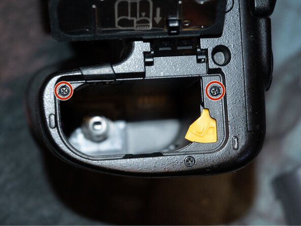
Remove the 7 J00 screws (circled in red) on the center baseplate cover on the base of the camera.
-
The center cover will come off easily. There are 4 rubber feet (circled in blue) that also fall off easily and may stick to the camera body. Push them back in their holes in the center cover.
-
-
-
-
Remove the 10 J00 screws holding the back case assembly to the camera body.
-
-
-
The rear case/display and card slot cover will come out at the same time. The rear case unfolds down, so watch those cables!
-
-
-
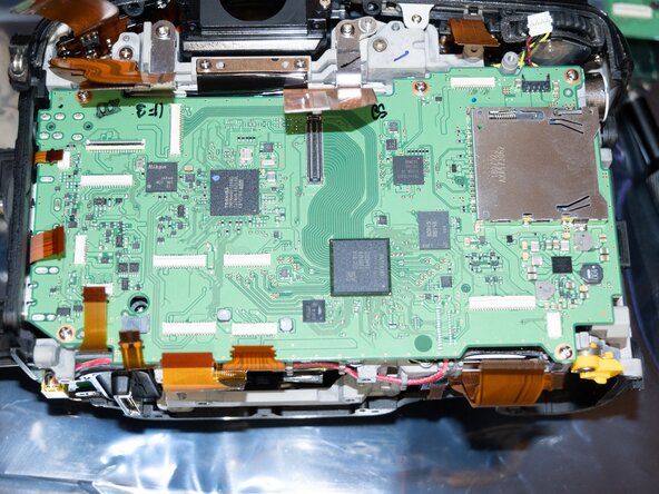
Time to get the connectors off the main board!
-
All the connectors with red arrows are the same style as the rear cover connector. Flip up the latch at the rear of the connector and the cable will come out easily.
-
The blue connector is the main image sensor connector. It pulls straight up off the board "like a little lego".
-
The purple connector is easiest to remove by placing tweezers under the connector where the wires come out, and prying straight up. It comes out vertically but is "clipped" in.
-
These yellow guys are the dangerous ones. They press into the connector from the side without a latch. The cables have small "ears" on them to help pull them out and insert them but use extreme care removing these cables from the board. They require some force to remove from the connectors.
-
-
-
Remove the 5 J00 screws around the edge of the mainboard. The mainboard will lift straight up and to the right out of the camera body.
-
-
-
Use care on reassembly not to catch any cables under the mainboard. I circled the ones that gave me problems.
-
On the connectors I earlier circled in yellow without release latches, I used soft-tipped tweezers to slowly wiggle them back into place. Be sure all connectors are fully seated!
-
The flip-up levers on the board need to be flipped up to insert the cables. Make sure the cables are fully seated before pushing the levers back down to secure the cables.
-
The main sensor connector (circled blue earlier) will snap down with some force into the mainboard. Make sure it is well aligned with the connector to prevent damage to either part.
-
-
-
Reinstall any removed accessories and verify every camera button and function is working correctly. Update firmware if the new board doesn't have the latest version.
-


To reassemble your device, follow these instructions in reverse order. Use extreme care on the friction-fit press in cables!
To reassemble your device, follow these instructions in reverse order. Use extreme care on the friction-fit press in cables!