Introduction
Tripped over your power cord? At least you don't have to replace the entire logic board.
What you need
-
-
Use a coin to turn the battery locking screw 90 degrees to the right.
-
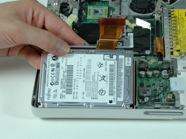
Lift the battery out of the computer.
-
-
-
Remove the four Phillips screws from the memory door.
-
Slide the memory door away from the memory compartment.
-
-
-
On the keyboard, remove the F1, F2, F11, and F12 keys.
-
This is scary - take a deep breath before continuing. Place your index finger under the upper left corner of the key and lift up until you hear a click. Then, transfer your finger to the left edge of the key and lift up to pull the key off.
-
You're freeing the two tabs on the left of the key from the two small holes in the plastic scissors mechanism.
-
-
-
Turn the computer over and open it up.
-
Remove the following 14 screws:
-
Six 2.5 mm Phillips on either side of the keyboard area.
-
Five 4.5 mm Phillips on the left half of the keyboard area.
-
One 7 mm hex in the upper left corner of the upper case (a T6 Torx driver will do the job nicely).
-
One 15 mm Phillips in the upper middle of the keyboard area.
-
One 16.5 mm hex in the upper right of the upper case (again, a T6 Torx driver will work well).
-
-
-
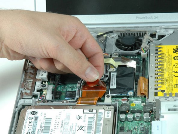
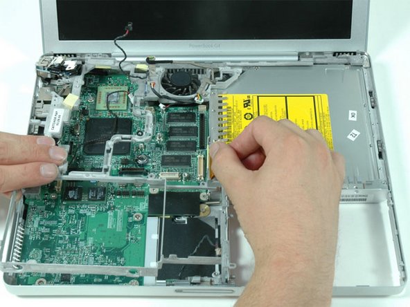
Peel up the two pieces of foil tape on the left side of the keyboard area.
-
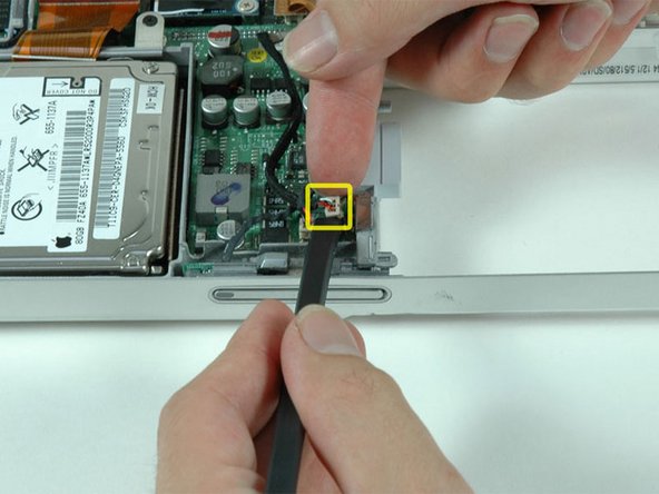
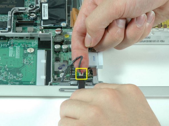
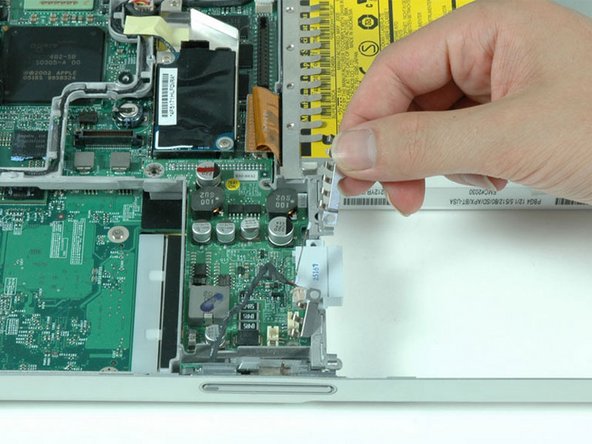
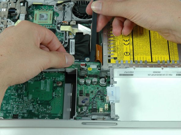
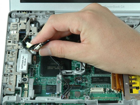
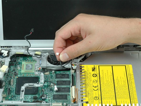
Carefully disconnect the microphone and power cables from the logic board. Using your fingernails or a dental pick, carefully pry the connectors from their sockets. Make sure you're pulling only on the connector and not on the socket.
-
-
-
-
Using a screw driver, gently release the two grey plastic clips inside the battery compartment in order to remove the right part of the upper case.
-
There are two more grey plastic clips holding the left part of the upper case. They are not easy to release as they are hidden from view prior to disassembly. They are in the same position as the two in the battery compartment, but on the opposite side of the trackpad. Try to stick a flat pry tool into the clip holes and push the clips inward (toward to screen) so they disengage and release the left part of the upper case.
-
Lift the upper case off the computer.
-
-
-
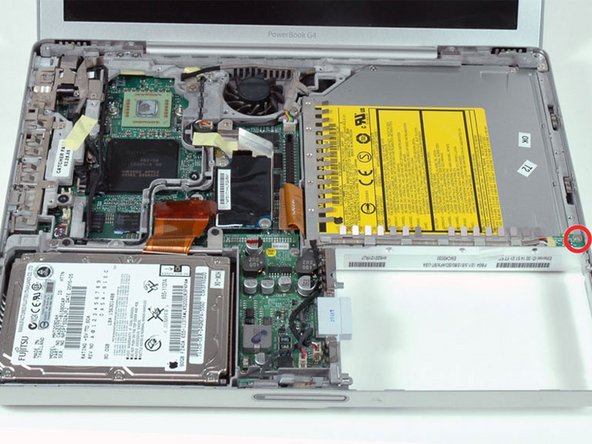
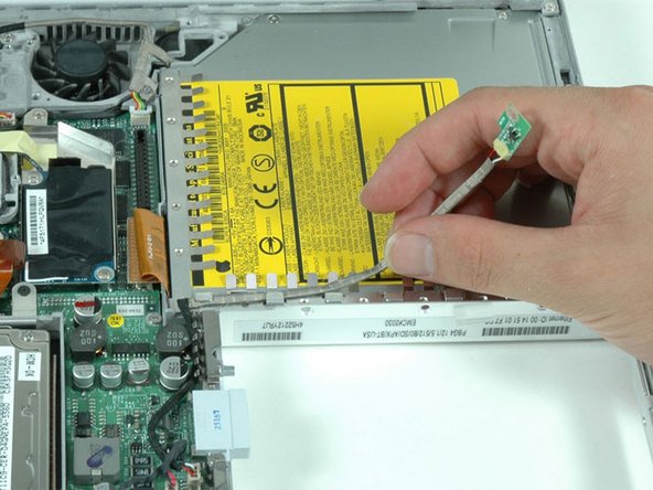
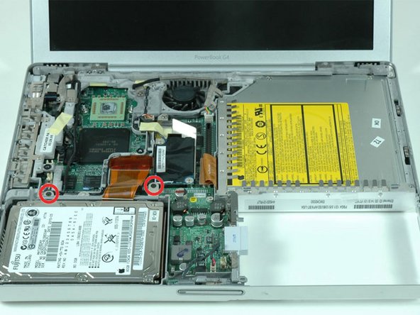
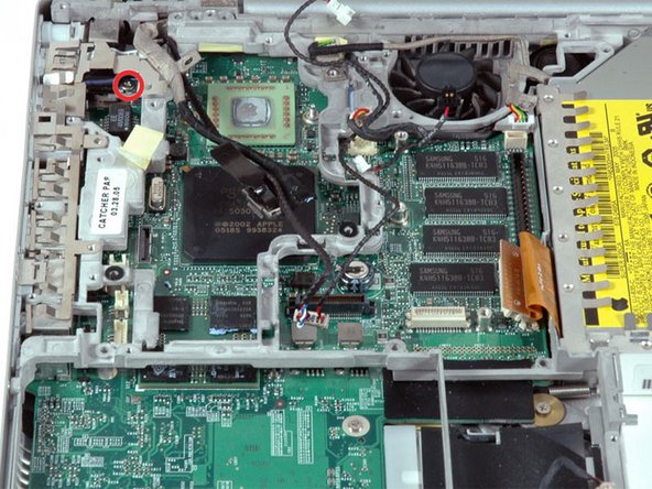
Remove the single Phillips screw securing the hall effect sensor board to the optical drive.
-
-
-
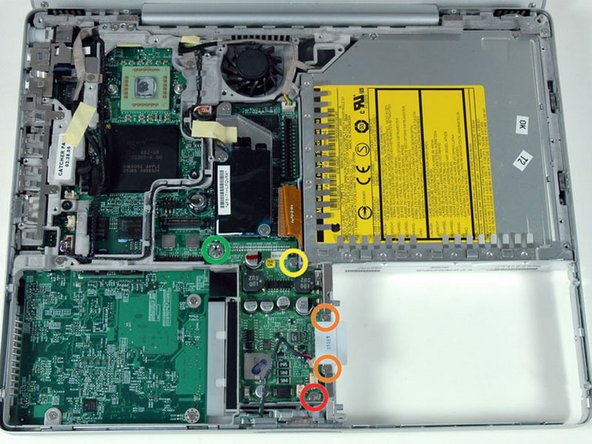
Remove the following five secrews/standoffs from the DC-to-DC board:
-
One 3.5 mm Phillips in the lower right corner.
-
Two 3 mm Phillips on either side of the battery contacts.
-
One 10 mm Phillips in the upper right corner.
-
One 14 mm long 4 mm standoff in the upper left corner. You can remove this standoff either with a 4 mm nut driver or needlenose pliers.
-
-
-
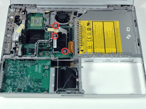
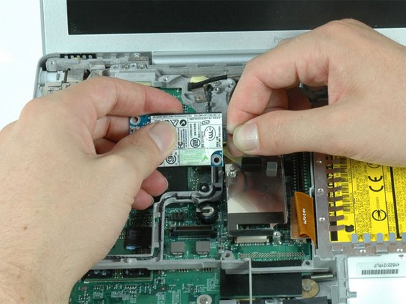
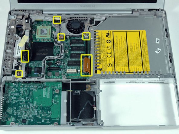
Remove the following nine screws:
-
Four 3 mm Phillips allong the left edge and near the fan.
-
One 4 mm Phillips in the bottom left corner.
-
Two 6 mm Phillips near the left hinge.
-
One 9 mm Phillips in the top left corner of the fan.
-
One 12 mm Phillips just above where the hard drive was located.
-
-
-
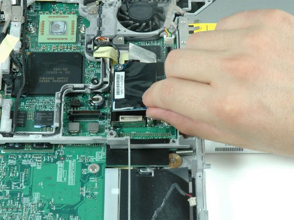
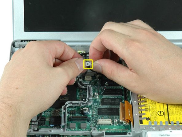
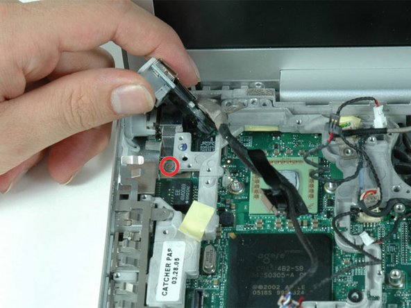
Remove the single Phillips screw that attaches the DC-In board to the lower case.
-


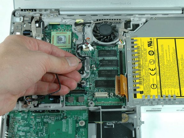

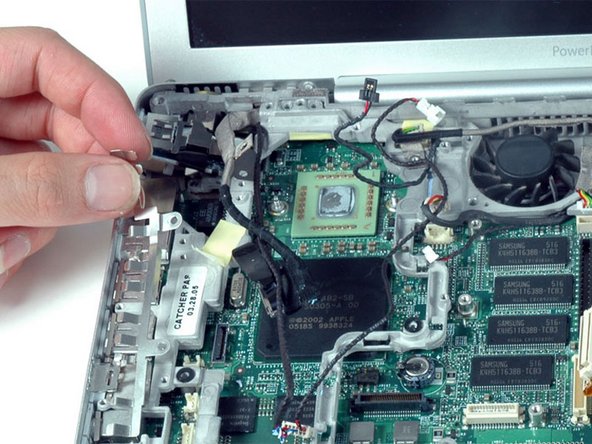


To reassemble your device, follow these instructions in reverse order.
To reassemble your device, follow these instructions in reverse order.
Cancel: I did not complete this guide.
29 other people completed this guide.
Attached Documents

2 Comments
Add a "good quality silver-based thermal paste" to the list of tools required. See step 25 and here:
Great tutorial. Took me about 4 hours but this was my very first tear down of a computer. The only thing I would recommend is that you get two anti-static trays for all the screws and recommend an anti-static mat as well. For newbys they might miss it. Thanks for your help.