Introduction
Follow this guide to remove or replace the earpiece speaker and vibration motor in your Samsung Galaxy S22 Ultra.
What you need
-
-
Heat an iOpener and apply it to the right edge of the back cover for two minutes.
-
-
-
While you wait for the adhesive to soften, note the following:
-
There's adhesive securing the back cover around the perimeter of the frame.
-
-
-
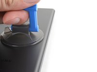
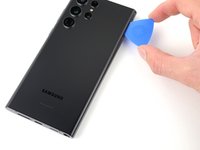
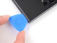
Apply a suction handle to the back cover, as close to the center of the right edge as possible.
-
Pull up on the suction handle with strong, steady force to create a gap between the cover and the frame.
-
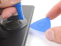
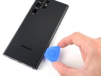
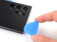
Insert an opening pick into the gap.
-
-
-
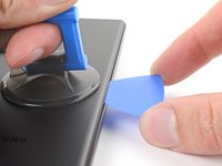
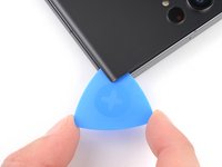
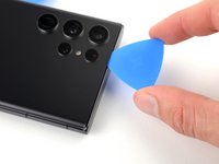
Slide the pick back and forth along the right edge to slice through the adhesive.
-
Leave the pick inserted near the bottom of the right edge to prevent the adhesive from resealing.
-
-
-
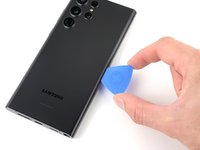
Apply a heated iOpener to the bottom edge of the back cover for two minutes.
-
-
-
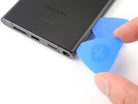
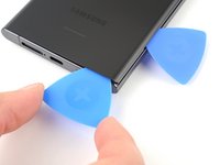
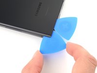
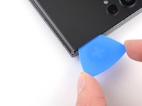
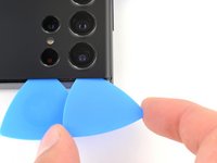
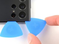
Insert a second opening pick at the bottom right corner.
-
Angle the pick upward to match the curved edge and rotate it around the bottom right corner.
-
-
-
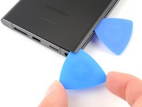
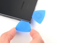
Slide your opening pick to the bottom left corner to slice the adhesive.
-
Leave the pick in the bottom left corner to prevent the adhesive from resealing.
-
-
-
Apply a heated iOpener to the left edge of the back cover for two minutes.
-
-
-
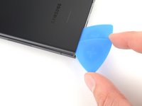
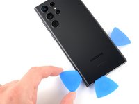
Insert a third opening pick at the bottom left corner.
-
Angle the pick upward to match the curved edge and rotate it around the bottom left corner.
-
-
-
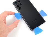
Slide your opening pick along the left edge to slice the adhesive, stopping when you reach the power button.
-
Leave the pick in the left edge to prevent the adhesive from resealing.
-
-
-
Heat an iOpener and apply it to the top edge of the back cover for two minutes.
-
-
-
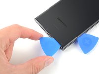
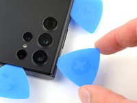
Insert an opening pick in the gap at the top right edge.
-
Angle the pick upward to match the curved edge and rotate it around the top right corner.
-
-
-
-
Slide the pick to the top left corner to slice the adhesive.
-
Leave the pick in to prevent the adhesive from resealing.
-
-
-
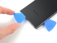
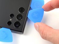
Insert an opening pick in the gap at the top left edge.
-
Angle the pick upward to match the curved edge and rotate it around the top left corner.
-
-
-
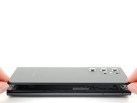
Slide the pick toward the bottom camera to slice through the remaining adhesive, stopping before you reach the power button.
-
-
Tool used on this step:Tweezers$4.99
-
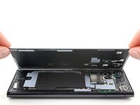
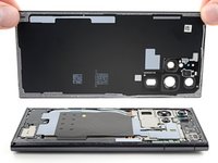
Grab and remove the back cover.
-
This is a good point to power on your phone and test all functions before sealing it up. Be sure to power your phone back down completely before you continue working.
-
Remove any adhesive chunks with a pair of tweezers or your fingers. Apply heat if you're having trouble separating the adhesive.
-
If you're using custom-cut adhesives, follow this guide.
-
If you're using double-sided tape, follow this guide.
-
-
-
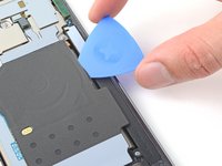
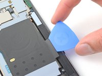
Insert an opening pick between the right edge of the wireless charging coil and the battery.
-
Slide the pick along the right edge to separate the adhesive.
-
-
-
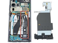
Use the pointed end of a spudger to pry and disconnect the NFC antenna press connector from the motherboard.
-
Repeat for the wireless charging coil press connector.
-
-
-
Use your Phillips screwdriver to remove the five 3.5 mm-long screws securing the NFC antenna and charging coil.
-
-
-
Use your Phillips screwdriver to remove the six 3.5 mm screws securing the loudspeaker.
-
-
-
Insert the pointed end of your spudger between the upper right corner of the loudspeaker and the frame.
-
Pry up to unclip the loudspeaker from the frame.
-
-
-
Grab and remove the NFC, wireless charging coil, and loudspeaker from the frame.
-
-
-
Use the pointed end of your spudger to pry up and disconnect the battery press connector.
-
-
-
Use the pointed end of your spudger to pry up and disconnect the laser autofocus module press connector.
-
-
-
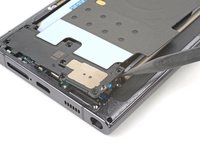
Use your Phillips screwdriver to remove the three 3.5 mm-long screws securing the motherboard cover.
-
-
-
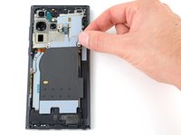
Insert the pointed end of your spudger between the bottom right corner of the motherboard cover and the frame.
-
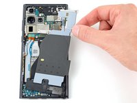
Pry up on the cover to unclip it from the frame.
-
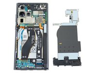
Remove the motherboard cover and laser AF module.
-
-
-
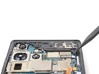
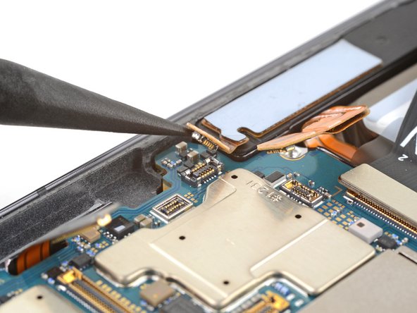
Use the pointed end of your spudger to pry up and disconnect the front-facing camera press connector.
-
-
-
Use the pointed end of your spudger to pry up and disconnect the fingerprint reader press connector.
-
-
-
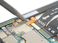
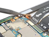
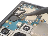
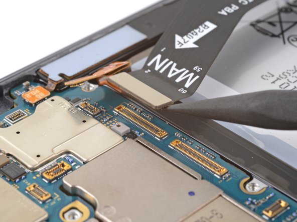
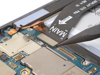
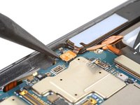
Use the pointed end of your spudger to pry up and disconnect the screen press connector.
-
-
-
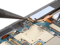
Use the pointed end of your spudger to pry up and disconnect the stylus' press connector.
-
-
-
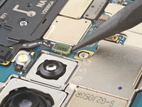
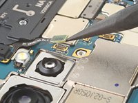
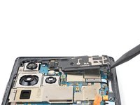
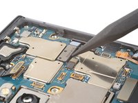
Use your Phillips screwdriver to remove the 3.5 mm-long screw securing the motherboard.
-
-
-
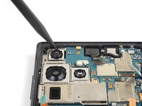
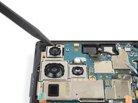
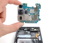
Insert the pointed end of your spudger between the top left of the motherboard and the frame.
-
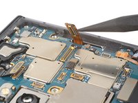
Pry the motherboard up until you can grab it with your fingers.
-
-
-
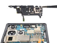
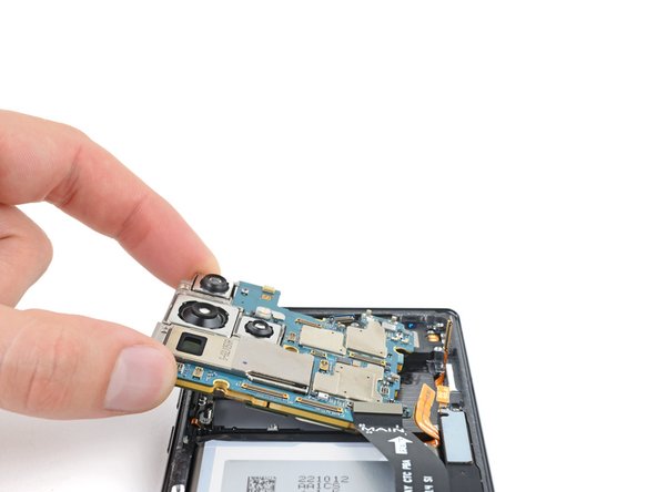
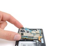
Grab the motherboard by the left edge and remove it from the frame.
-
-
-
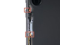
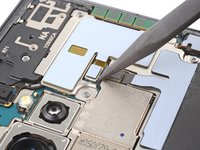
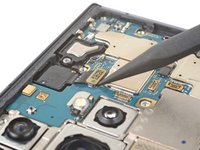
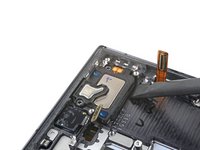
Use your Phillips screwdriver to remove the two 3.2 mm-long screws securing the earpiece speaker and vibration motor.
-
-
-
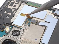
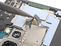
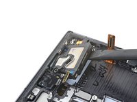
Insert the flat end of your spudger underneath the bottom edge of the earpiece speaker and vibration motor.
-
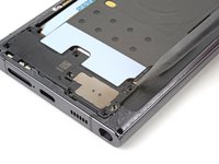
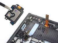
Pry the earpiece speaker and vibration motor up from its recess and remove it.
-


To reassemble your device, follow these instructions in reverse order.
Take your e-waste to an R2 or e-Stewards certified recycler.
Repair didn’t go as planned? Check out our Answers community for troubleshooting help.
To reassemble your device, follow these instructions in reverse order.
Take your e-waste to an R2 or e-Stewards certified recycler.
Repair didn’t go as planned? Check out our Answers community for troubleshooting help.
Cancel: I did not complete this guide.
3 other people completed this guide.

Team

One Comment
This guide is outright wrong. The vibration motor is a part of the LOUDSPEAKER Assembly NOT the earpiece