
Samsung Galaxy S23 Plus Screen and Battery Assembly Replacement

Introduction
Go to step 1Follow this guide to replace the screen and battery assembly on your Samsung Galaxy S23+.
This guide is written for the screen and battery assembly. The assembly consists of the screen, battery, and frame together in one part. Be sure you have the right part before you begin the repair. If you're only replacing the screen, follow this guide.
Before disassembling your device, completely discharge the battery. This reduces the risk of a dangerous thermal event if the battery is accidentally damaged during the repair. If your battery is swollen, take appropriate precautions.
Note: Retaining water resistance after the repair will depend on how well you reapply the back cover adhesive, but your device will lose its IP (Ingress Protection) rating.
What you need
Tools


Show more…
-
-
Unplug any cables from your phone.
-
Hold the side key and the volume down button, then select "Power off" to turn off your phone.
-
-
-
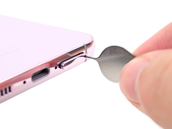
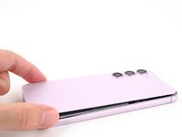
Insert a SIM eject tool, bit, or straightened paper clip into the SIM card tray hole on the bottom edge of the phone.
-
Press firmly to eject the tray.
-
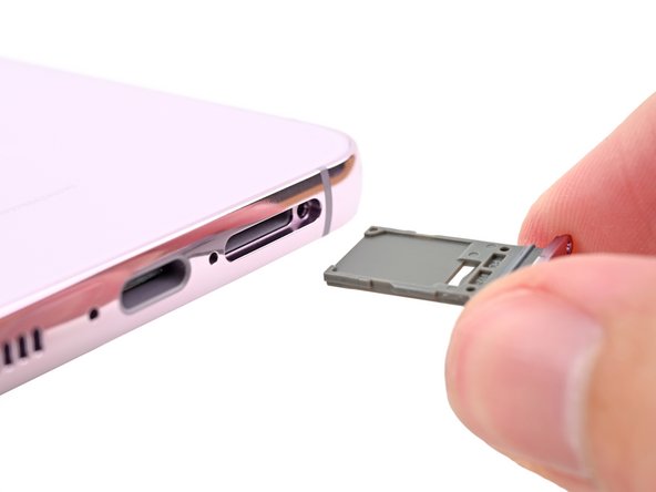
Remove the SIM card tray.
-
-
-
Heat an iOpener and apply it to the right edge of the back cover for two minutes to soften the adhesive.
-
-
-
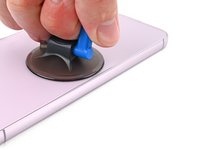
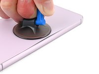
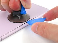
Apply a suction handle to the back cover, as close to the center of the right edge as possible.
-
Pull up on the suction handle with strong, steady force to create a gap between the cover and the frame.
-
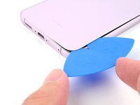
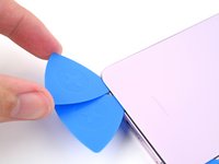
Insert an opening pick into the gap.
-
-
-
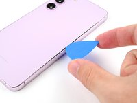
Slide the pick back and forth along the right edge to separate the adhesive.
-
Leave the pick inserted near the bottom right corner to prevent the adhesive from resealing.
-
-
-
Apply a heated iOpener to the bottom edge of the back cover for two minutes.
-
-
-
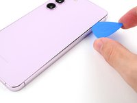
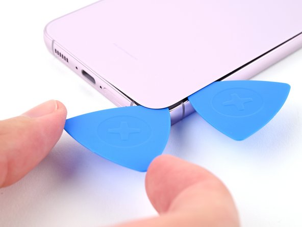
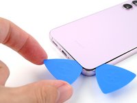
Insert a second pick at the bottom right corner.
-
Rotate the opening pick around the bottom right corner to separate the adhesive.
-
-
-
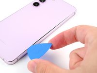
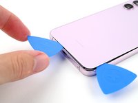
Slide the opening pick to the bottom left corner to separate the adhesive.
-
Leave the pick in the bottom left corner to prevent the adhesive from resealing.
-
-
-
Apply a heated iOpener to the left edge of the back cover for two minutes.
-
-
-
Rotate the opening pick around the bottom left corner to separate the adhesive.
-
-
-
Insert a third opening pick at the bottom left corner.
-
Slide your pick toward the top left corner to separate the adhesive.
-
Leave the pick in the top left corner to prevent the adhesive from resealing.
-
-
-
Heat an iOpener and apply it to the top edge of the back cover for two minutes.
-
-
-
Insert a fourth opening pick at the top left corner.
-
Rotate it around the top left corner to separate the adhesive.
-
-
-
Slide your opening pick to the top right corner to separate the adhesive.
-
Leave the pick in the top right corner to prevent the adhesive from resealing.
-
-
-
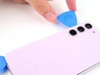
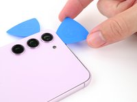
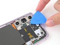
Line up the tip of an opening pick with the flash cutout.
-
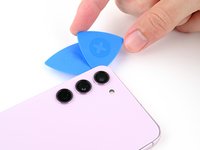
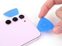
Slide the opening pick under the top of the back cover until you feel it start to snag on the adhesive.
-
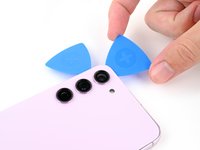
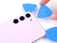
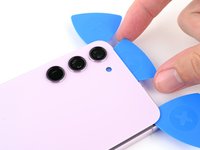
Keep sliding the pick toward the bottom of the phone until you feel the adhesive completely separate from the back cover.
-
-
-
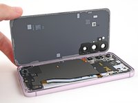
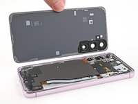
Grab and remove the back cover.
-
This is a good point to power on your phone and test all functions before sealing it up. Be sure to power your phone back down completely before you continue working.
-
Remove any adhesive chunks with a pair of tweezers or your fingers. Apply heat and isopropyl alcohol (90% or greater) if you're having trouble removing the adhesive.
-
If you're using custom-cut adhesives, follow this guide.
-
If you're using double-sided tape, follow this guide.
-
-
-
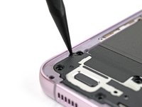
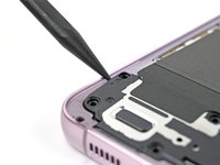
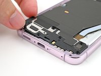
Use the point of your spudger to pry up and disconnect the wireless charging coil press connector from the motherboard.
-
-
-
Use the point of a spudger to pry up and disconnect the NFC antenna press connector.
-
-
-
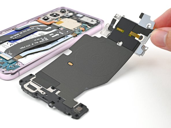
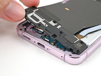
Use a Phillips screwdriver to remove the thirteen 3.5 mm‑long screws securing the wireless charging coil and the loudspeaker:
-
Six screws securing the wireless charging coil
-
Seven screws securing the loudspeaker
-
-
-
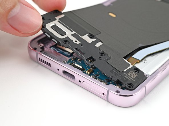
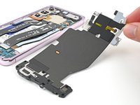
Insert the point of your spudger in the notch at the top left corner of the loudspeaker.
-
Pry up to unclip the loudspeaker from the frame.
-
-
-
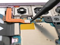
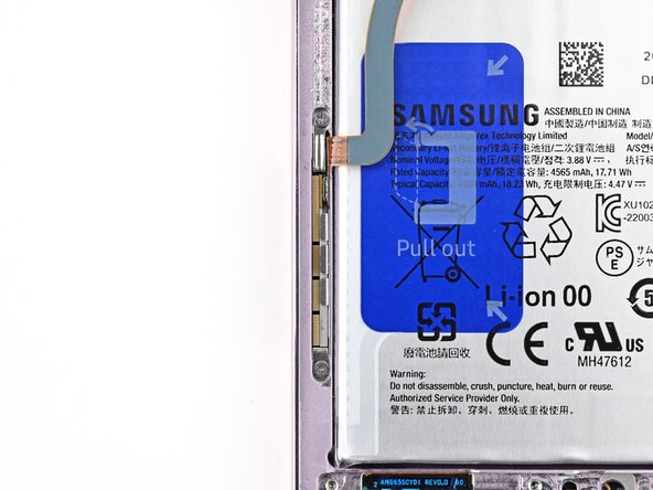
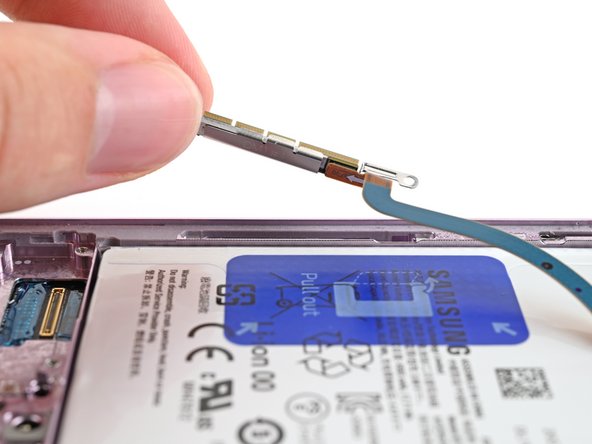
Use the point of your spudger to pry up and disconnect the battery press connector.
-
-
-
Use the tip of a spudger to pry up and disconnect the earpiece speaker press connector.
-
-
-
Use a Phillips screwdriver to remove the five 3.5 mm‑long screws securing the earpiece speaker.
-
-
-
Insert the flat end of your spudger between the bottom edge of the earpiece speaker and the sliver shield on the motherboard.
-
Twist the spudger to unclip the earpiece speaker from the frame and remove it.
-
-
-
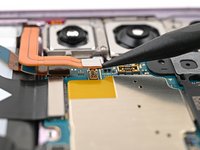
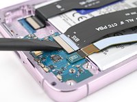
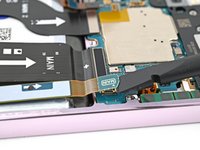
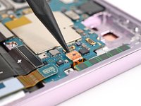
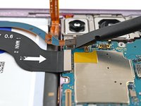
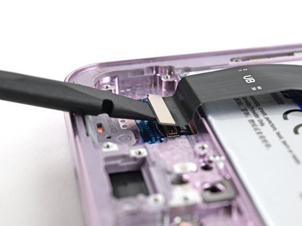
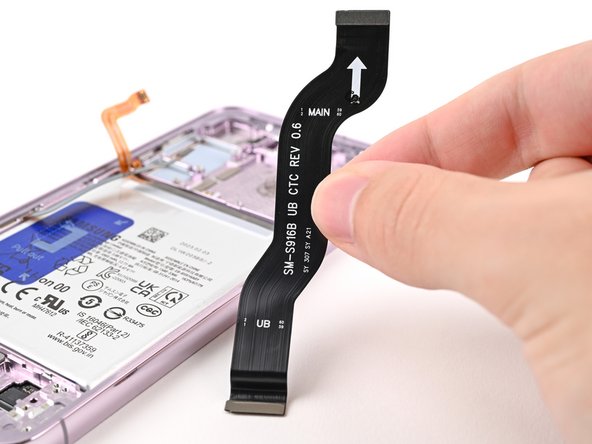
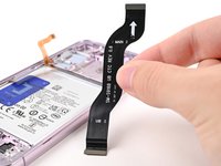
Use your spudger to pry up and disconnect the primary and secondary interconnect cable press connectors from the daughterboard.
-
-
-
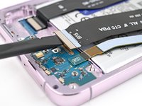
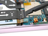
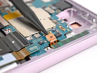
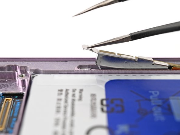
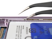
Insert the tip of your spudger between the left edge of the antenna press connector and the sliver plate on the motherboard.
-
Pry up and disconnect the antenna press connector.
-
-
-
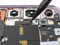
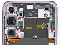
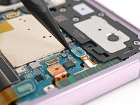
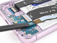
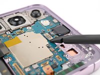
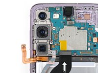
Use your spudger to pry up and disconnect the display and 5G mmWave cable press connectors from the motherboard.
-
-
-
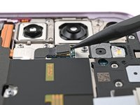
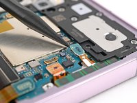
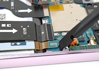
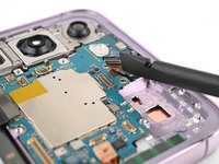
Use your spudger to pry up and disconnect the front camera press connector.
-
-
-
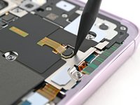
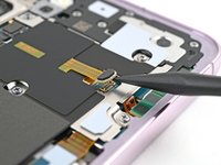
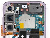
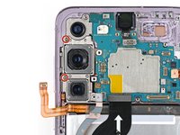
Use a Phillips screwdriver to remove the two 3.5 mm‑long screws securing the motherboard.
-
-
-
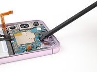
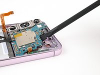
Insert the flat end of your spudger between the top edge of the motherboard and the frame, near the earpiece speaker cutout.
-
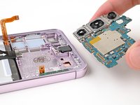
Twist the spudger to lift the motherboard up and out of the frame until you can grip it with your fingers.
-
Remove the motherboard.
-
-
-
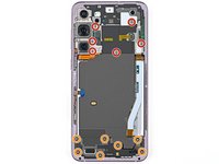
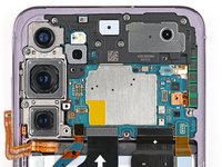
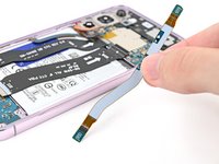
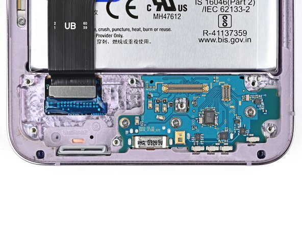
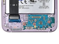
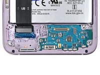
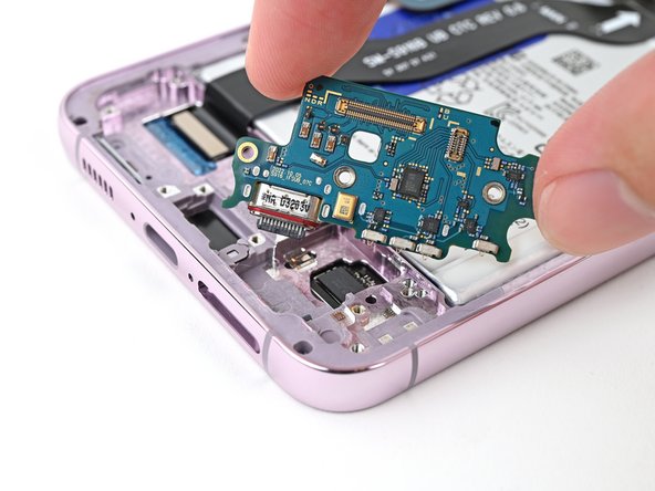
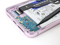
Use a Phillips screwdriver to remove the three 3.5 mm‑long screws securing the daughterboard.
-
-
-
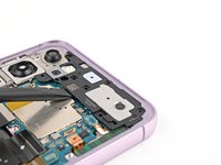
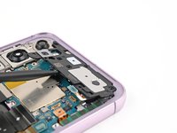
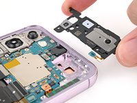
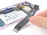
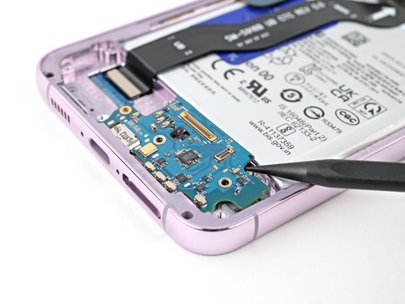
Use the point of a spudger to pry up the top right corner of the daughterboard and unclip it from the frame.
-
Remove the daughterboard.
-
-
-
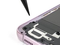
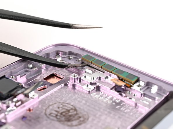
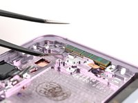
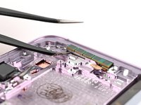
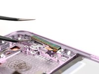
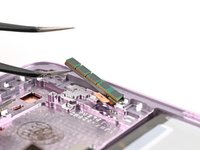
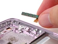
Insert one arm of your angled tweezers in the notch between the top edge of the upper 5G mmWave antenna and the frame.
-
-
-
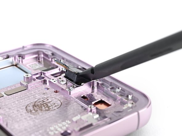
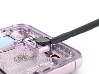
Use a hair dryer or a heat gun to heat the front camera for 90 seconds.
-
-
-
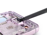
Use the flat end of your spudger to pry the front camera from its recess in the frame.
-
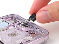
Remove the front camera.
-
-
-
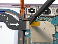
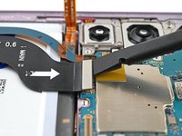
Use the flat end of a spudger to pry up and disconnect the display cable press connector from the back of the screen.
-
Remove the display cable.
-
-
-
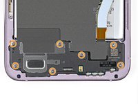
Use a Phillips screwdriver to remove the two 2.5 mm‑long screws securing the 5G mmWave antenna.
-
-
-
Insert one arm of a pair of angled tweezers into the bottom screw hole on the 5G mmWave antenna bracket.
-
Pry up with the tweezers and lift the antenna bracket out of its recess enough until you can grip it with your fingers.
-
-
-
You're now left with the screen and battery assembly.
-


Compare your new replacement part to the original part—be sure to transfer remaining components and remove adhesive backings from the new part before installing.
To reassemble your device, follow these instructions in reverse order.
Take your e-waste to an R2 or e-Stewards certified recycler.
Repair didn’t go as planned? Try some basic troubleshooting, or ask our Samsung Galaxy S23+ Answers Community for troubleshooting help.

