Nintendo Switch OLED Model Game Card Reader Daughterboard Replacement

27 Steps

Time Required: 45 minutes - 1 hour

Use this guide to replace the game card reader daughterboard in your Nintendo Switch OLED.

For your safety, discharge the battery below 25% before disassembling your Switch. This reduces the risk of fire if the battery is accidentally damaged during the repair. If your battery is swollen, take appropriate precautions.

The Switch OLED uses JIS screws, but you can use a Phillips screwdriver in a pinch. Be very careful not to strip the screws. iFixit's Phillips bits are designed to be cross-compatible with JIS-style screws.

Note: When you remove the shield plate, you’ll need to replace the thermal compound between the plate and the heatsink. Since normal thermal paste isn’t designed to bridge large gaps, the closest replacement is K5 Pro viscous thermal paste.

Step 1 Release the Joy Con controller locking tabs

Before you begin this repair, make sure the device is completely powered off.
Press and hold down the small round button on the back of the Joy Con controller.
While you hold down the button, slide the controller upward.

Step 2 Remove the Joy Con controllers

Continue sliding the Joy Con upward until it's completely removed from the console.
Repeat this same process for the other Joy Con.

Step 3 Remove the top screw

Use a Phillips driver, or a JIS driver, to remove the 2 mm-long screw securing the top of the rear case to the frame.
To prevent these tight screws from stripping, apply firm downward force, work slowly, and try another JIS or Phillips driver if the screws won't come out.

Step 4 Remove the bottom screws

Use a Phillips driver to remove the two 2 mm-long screws securing the bottom of the rear case to the frame.

Step 5 Remove the right screw

Use a Phillips driver to remove the 3.8 mm screw securing the right Joy-Con sensor rail to the rear case.
To prevent these tight screws from stripping, apply firm downward force, work slowly and try another JIS 000 or PH 000 driver if the screws won't come out.

Step 6 Remove the left screw

Use a Phillips driver to remove the 3.8 mm screw securing the left Joy-Con sensor rail to the rear case.

Step 7 Open the kickstand

Use your finger to flip up the kickstand on the back of the device.
If there's a microSD card in the microSD card slot, remove it now before you continue to the next step.

Step 8 Remove the back-side screws

Use a Y00 screwdriver to remove the two 4.3 mm screws securing the rear case to the frame.

Step 9 Remove the rear case

Lift the rear case up from the top of the device and remove it.
If you're having trouble removing the case, use an opening pick to pry up the plastic clips.

Step 10 Remove the shield plate's tape

Use the flat end of a spudger to separate a corner of the tape from the shield plate.

Step 11

Use tweezers, or your fingers, to peel back and remove the tape.
Store the tape in a clean space for reinstallation.

Step 12 Disconnect the primary Wi-Fi antenna

Use tweezers, or your fingers, to pull up and disconnect the primary Wi-Fi antenna's coaxial cable.
During reassembly, these can be tricky to reconnect. One at a time, hold each connector in place over its socket and press down with the flat end of a spudger. The connector should snap into place.

Step 13 Reroute the primary antenna's coaxial cable

Use tweezers, or your fingers, to reroute the primary antenna's coaxial cable out of its slots in the shield plate.

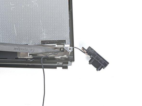
Step 14 Unfasten the primary Wi-Fi antenna

Use a Phillips driver to remove the two 4.4 mm screws securing the primary Wi-Fi antenna to the shield plate.

Step 15 Remove the primary Wi-Fi antenna

Insert an opening pick between the primary Wi-Fi antenna and the shield plate.
Pry up with the pick to separate the primary Wi-Fi antenna from the shield plate.

Step 16

Remove the primary Wi-Fi antenna.

Step 17 Disconnect the secondary Wi-Fi antenna

Use tweezers, or your fingers, to pull up and disconnect the secondary Wi-Fi antenna's coaxial cable.

Step 18 Reroute the secondary Wi-Fi antenna's coaxial cable

Use the point of a spudger to reroute the secondary Wi-Fi antenna's coaxial cable from its slot in the frame.

Step 19 Unfasten the secondary Wi-Fi antenna

Use a Phillips driver to remove the 4.4 mm screw securing the secondary Wi-Fi antenna to the shield plate.

Step 20 Remove the secondary Wi-Fi antenna

Insert an opening pick between the secondary Wi-Fi antenna and the shield plate.
Pry up with the pick to separate the secondary Wi-Fi antenna from the shield plate.
Don't attempt to completely remove the antenna yet, as its coaxial cable is still routed through the frame.

Step 21

Use the point of a spudger to reroute the secondary Wi-Fi antenna's coaxial cable out of its slot in the frame.
Remove the secondary Wi-Fi antenna.

Step 22 Unfasten the shield plate

Use a Phillips driver to remove the six 4.4 mm screws securing the shield plate to the frame.

Step 23

Use your fingers to lift the top of the shield plate up and away from the frame.
You may feel a bit of resistance. This is normal, since the shield plate is slightly bonded to the heat sink with thermal paste.
Remove the shield plate.
A thick pink thermal compound bridges the gap between the shield plate and the copper heat sink underneath. Whenever the shield plate is removed, refer to our thermal paste guide to remove the old thermal compound and replace it with an appropriate compound, such as K5 Pro, during reassembly.

Step 24 Disconnect the battery

Use the point of a spudger to pry up and disconnect the battery.

Step 25 Remove the tape

Use tweezers, or your fingers, to remove the piece of tape obscuring the daughterboard's screw.

Step 26 Unfasten the daughterboard

Use a Phillips driver to remove the 4 mm screw securing the daughterboard to the frame.

Step 27 Remove the daughterboard

The bottom of the daughterboard is connected to the motherboard via a press connector.
Insert a spudger between the edge of the daughterboard and the motherboard.
Pry up with the spudger to disconnect the press connector and separate the daughterboard from the frame.
Remove the daughterboard.
To re-attach press connectors like this one, carefully align and press down on one side until it clicks into place, then repeat on the other side. Do not press down on the middle. If the connector is misaligned, the pins can bend, causing permanent damage.

To reassemble your device, follow these instructions in reverse order.

Compare your new replacement part to the original part—you may need to transfer remaining components or remove adhesive backings from the new part before you install it.

Repair didn’t go as planned? Try some basic troubleshooting, or ask our Nintendo Switch OLED Answers community for help.