Introduction
The motherboard includes all ports except the DC-In board.
What you need
-
-
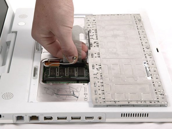
Pull the keyboard release tabs toward you and lift up on the keyboard until it pops free.
-
Flip the keyboard over, away from the screen, and rest it face-down on the trackpad area.
-
-
-
Use a pin (or anything you like) to remove the three rubber feet from the lower case.
-
-
-
Remove the three hex screws using a T8 Torx screwdriver (or Allen screws using an Allen key if these are used).
Quote from dalekaty:
Why use a T8 Torx when these screws are metric hex 2? The T8 didn't work at all. Other than that this was a very easy repair. It cost $29 instead of the $150 that I paid the last time a Mac shop made the same repair.
Had the same issue with a T8, although I blamed that on my T8 being quite stripped. Finding an appropriate bit was quite a challenge... but I'm pretty certain a T8 isn't correct. The screws have a hex head, not a Torx... maybe T8 is the closest thing that tends to fit...
Not Torx, but allen key (British wrench), 2mm
I attempted this last night following all the steps correctly, when I was done my ibook would not turn on. Now sure where I went wrong? Any ideas. Thank you
-
-
-
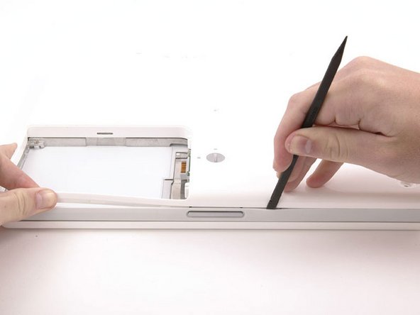
Push the thin rims of the lower case surrounding the battery compartment in, bending them past the tabs, and then lift up to free that corner of the lower case.
I printed these instructions out, and this one was at the top of page 2. I found the first paragraph amusing enough that I had to show my boss.
-
-
-
Continue to run the spudger around the front, right corner. There are two tabs on the port side of the computer, one near the front corner and one near the sound-out port.
For me, this was really the toughest part! Trying to find/get a good grip on the iBook and really *forcing* that spudger around. All without scratching the display.
Once you loosen the the front the seam is very tight. I was able to slide the spudger in the middle of the port side instead of starting at the corner.
-
-
-
-
Once the front and sides of the lower case are free, turn the computer so that the back is facing you and pull the lower case up and toward you until the back tabs pop free (it may be helpful to jiggle the case up and down).
This was the scariest part for me. I had to wiggle it a lot as it seemed to be stuck. But it did come loose.
There are 4 tabs in the back. It'll come off easier if you use an spudger to release those.
-
-
-
Remove the following 10 screws from the bottom shield:
-
Six 3 mm Phillips
-
Three 7.5 mm Phillips
-
One 14 mm Phillips
-
-
-
Lift the bottom shield off.
My dc board had 2 screws. for some reason when i tried to screw them both back in only one got tight. the other one just kept twirling so i left it out. i didnt want to have a loose screw rattling around in my computer.
also had trouble laying down the wire to the dc board. it wouldnt lay flat but i was able to get it flat enough. overall it worked and the computer is now up and running!
thank you! it was pretty easy
-
-
-
Remove the single Phillips screw securing the DC-In board.
At this point alternate hard drive can be connected to logic board for testing. Alternate hard drive and drive cable req'd. Remove hard drive cable from logic board. Plug in alternate cable and drive.
-
-
-
Disconnect the DC-In cable from the logic board.
-
-
-
Deroute the cable from around the optical drive, removing tape as necessary, and angle the DC-In board out of its compartment.
Went pretty smoothly as described. I used an egg crate marked for each step where screws were removed to keep them all sorted out (OCD vs. old age). Only other tip was that in step #5 the rings and screws at the corners of the back seemed to be integrated and came out together, the rubber feet came up by pulling from the side - didn't really require a thumb tack. Otherwise, having the right tools (described) made it a snap.
Quote from drscole:
Went pretty smoothly as described. I used an egg crate marked for each step where screws were removed to keep them all sorted out (OCD vs. old age). Only other tip was that in step #5 the rings and screws at the corners of the back seemed to be integrated and came out together, the rubber feet came up by pulling from the side - didn't really require a thumb tack. Otherwise, having the right tools (described) made it a snap.
I agree - having the right tools is the key to this going smoothly. It would have useful to have more detail around where the long and short screws go on the heat shield. This is minor niggle and overall good instructions.
Quote from drscole:
Went pretty smoothly as described. I used an egg crate marked for each step where screws were removed to keep them all sorted out (OCD vs. old age). Only other tip was that in step #5 the rings and screws at the corners of the back seemed to be integrated and came out together, the rubber feet came up by pulling from the side - didn't really require a thumb tack. Otherwise, having the right tools (described) made it a snap.
The egg crate is a good idea. I use a piece of cardboard and I label each step and layout the screws visually as I pulled them out.
-
-
-
Remove the following 11 screws from the bottom of the computer:
-
Three 3 mm Phillips around the battery compartment. (Some models may only have two screws.)
-
Three 4.5 mm Phillips along the optical drive bezel. (a magnetic screwdriver may help to lift these screws out)
-
One 11 mm Phillips in the lower right corner. (if present)
-
Four 14.5 mm Phillips.
The middle screw along the optical drive got sucked sideways into an opening by something magnetic and proved impossible to get out with a bit of blutack on the end of a screwdriver. In the end turning it over and giving it a smart tap worked.
-
-
-
Turn over the computer and open it.
-
Remove the 2 Phillips screws (3mm) from the edges of the keyboard area.
-
Remove the 4 mm Phillips screw from the lower left corner.
-
-
-
Lift the upper case enough to disconnect the blue and white power cable from the logic board. Using your fingernails or a dental pick, carefully pry the connector from its socket. Make sure you're pulling only on the connector and not on the socket.
I skipped this and the next step altogether. Instead of taking the risk of breaking the power and/or speaker sockets, I left them connected. I put a stack of big books just to the left of the iBook. I swiveled the top case off and let it lean against the books. I removed the top shield and carefully swiveled it off and to the left, so it is now leaning on the top case. I had to move the power cable out of the way, and re-orient the top case so it's resting on it's back edge while the shield was resting on it's left edge. Then I slid the iBook towards the edge of the table and disconnected the HD ribbon from below! I then proceeded with removing the HD and putting in the new one.
When putting the rings back you will need to figure out their correct orientation. Just rotate each ring until you find the position that will make it flush with the case. There are three possible positions but only one of them is the right fit.
As the other comments make plain, you can't overemphasize that the power connector is in tight, and it is much easier to pull the connector off the board. That's what happened to me -- I'm really bad at soldering, so I will be looking for a replacement board. Oh well.
-
-
-
Carefully disconnect the multicolored speaker cable from the logic board. As before, make sure you're pulling only on the connector and not on the socket.
-
-
-
Remove the following 16 screws:
-
Thirteen 3 mm Phillips.
-
One 3 mm Phillips. (actual screw not present in image)
-
Two 4 mm Phillips.
Missing in this photo is the Bluetooth antenna present in some iBooks. It is located at the upper right corner of the battery compartment, just above the 4mm screw. You can see the bracket for the antenna in the photo. It is the two I-shaped holes just above the 4mm screw that must be removed in this step. To remove the antenna, slide it toward the LCD, and tilt it vertically back towards yourself. In the next step, where the shield is removed, you will need to slide the antenna through the lower I-shaped hole.
-
-
-
Lift the top shield up from the right side, minding the upper left corner, which may catch on the metal framework.
-
If your iBook has Bluetooth, as discussed in the previous step, you will need to slide the antenna through the lower I-shaped hole in the shield before completely removing the shield.
-
-
-
Turn the computer over and disconnect the fan cable from the logic board.
-
If present, remove the 4 Phillips screws securing the fan to the metal framework (one screw is hidden by the hand in the image) and lift the fan out of the computer. If no screws are present, continue on.
-
-
-
Turn the computer over and remove the two Phillips screws from the white plastic fingers of the hinge grill.
-
-
-
Remove the following 6 screws and 3 nuts from the heat sink:
-
One 2 mm Phillips extending from a finger on the left edge of the heatsink and adjacent the firewire port (not present on some models)
-
Three 3 mm Phillips from around the fan (some models may only have 2 screws).
-
One 3.5 mm Phillips on the left side of the heat sink (not present on some models).
-
One 4.5 mm Phillips at the top right corner of the heat sink.
-
One 6 mm Phillips at the lower left corner of the heat sink.
-
One 4 mm nut from the right side of the heat sink.
-
Two 4 mm screw nuts with attached springs from either side of the heat sink.
Mine did not had the screw marked in black and it did had 2 extra 3mm screws holding some sort of bracket where we see the lower pipe on the heatsink in this picture. Also it only had one pipe instead of two and only one heatsink that covers the whole thing instead of two.
Oh and the nuts seem to be imperial not metric - 3.5mm is too small and 4mm is a bit too big (4mm does do the job though).
-
-
-
Remove the two Phillips screws securing the white plastic fingers of the I/O bezel to the metal framework.
-
-
-
Wedge a spudger between the RJ-11 board and the metal framework and slide the board to the left, off of the logic board.
The RJ-11 socket looks glued in and I didn't see the need to remove it.
Sorry for my broken english, I'm italian.
Anyway following ifixit guide through I got successfully to the end and my ibook is working ok now.
The only problem I still have is with the keyboard.
There are some of the keys which don't correspond to the keys I select. I tried by selecting different keyboard flags: USA, italian, italian pro. The one working better is the USA one.
Can the the problem be generated because the new logic board comes from USA and the old Ibook and its keyboard were bought in Italy ??
Any suggestion is well accepted.
Special thanks to Ifixit
Sergio
-
-
-
Close the display and flip the computer over.
-
Remove the following 8 screws:
-
Four 4 mm Phillips.
-
One 3.5 mm Phillips near the sleep light connector (may not be in your specific model).
-
One 3 mm Phillips with a large head in the lower left corner.
-
One wide 4 mm Phillips.
-
One 3 mm Phillips.
-


To reassemble your device, follow these instructions in reverse order.
To reassemble your device, follow these instructions in reverse order.
Cancel: I did not complete this guide.
19 other people completed this guide.
Attached Documents

2 Comments
First of all, outstanding! I couldn't have done it otherwise. I especially liked the photography. I am a pro in that field and I know the good stuff when I see it.
I just have a few small suggestions.
1) You might want to warn about grounding for rank amateurs like me.
2) The screw sheets were fantastic but it might help to add the step/s involved. Also I found double sided foam tape was great for keeping the screws in place.
3) When removing the back cover I used kitchen matches camphored at one end as shims as I went along so I would not lose ground as I continued around the bottom cover. I also found a fifth of Jack Daniel's helped to steady my hands and give me patience.
4) The whole thermal compound thing was confusing. I looked up the suggested procedure and didn't know what to do about "the blue pads". I posted a question and got conflicting answers. It would be great if this could get resolved once and for all.
5) You might want to talk about installing the RAM when replacing the logic board
Thanks!