
iPad 6 Wi-Fi Logic Board Replacement

Introduction
Go to step 1Use this guide to replace a faulty logic board in your iPad 6 Wi-Fi.
Note that the logic board is paired to your iPad's home button, so replacing your logic board will result in losing the iPad's Touch ID functionality.
What you need
Parts

Tools


Show more…
-
-
Heat an iOpener and apply it to the left edge of the device for two minutes.
-
-
-
While you're waiting for the adhesive to loosen, note the following areas that are sensitive to prying:
-
Front camera
-
Antennas
-
Display cables
-
-
Tool used on this step:Clampy - Anti-Clamp$24.95
-
Pull the blue handle backwards to unlock the Anti-Clamp's arms.
-
Place an object under your iPad so it rests level between the suction cups.
-
Position the suction cups near the middle of the left edge—one on the top, and one on the bottom.
-
Hold the bottom of the Anti-Clamp steady and firmly press down on the top cup to apply suction.
-
-
-
Wait one minute to give the adhesive a chance to release and present an opening gap.
-
If your screen isn't getting hot enough, you can use a hair dryer to heat along the left edge of the iPad.
-
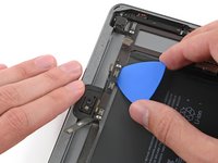
Insert an opening pick under the digitizer when the Anti-Clamp creates a large enough gap.
-
Skip the next step.
-
-
-
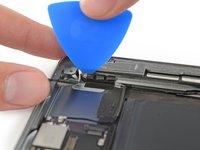
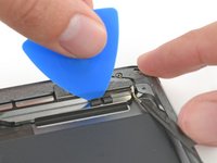
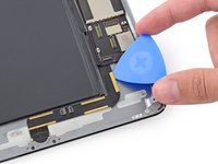
Once the screen is warm to touch, apply a suction handle to the left edge of the screen and as close to the edge as possible.
-
Lift the screen with the suction handle to create a small gap between the digitizer and the frame.
-
Insert an opening pick into the gap between the digitizer and the frame.
-
-
-
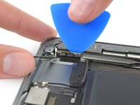
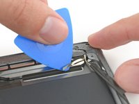
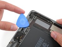
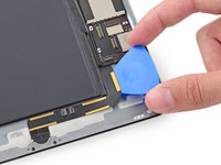
Insert a second opening pick into the gap you just created.
-
Slide the pick toward the bottom-left corner of the device to separate the adhesive.
-
Leave the pick in the bottom-left corner to prevent the adhesive from re-sealing.
-
-
-
Heat an iOpener and apply it to the top edge of the device for two minutes.
-
-
-
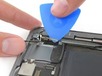
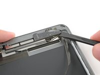
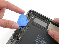
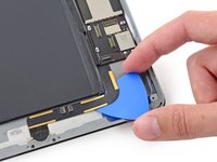
Rotate the pick around the top-left corner of the device to separate the adhesive.
-
-
-
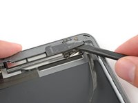
Slide the opening pick along the top edge of the device, stopping just before you reach the front camera.
-
-
-
Heat an iOpener and apply it to the right edge of the device for two minutes.
-
-
-
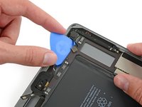
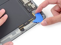
Rotate the pick around the top-right corner of the device to separate the adhesive.
-
-
-
Insert a new opening pick and slide it to the middle of the iPad's right edge.
-
-
-
Heat an iOpener and apply it to the bottom edge of the device for two minutes.
-
-
-
Slide the bottom-left pick to the bottom-left corner to separate the adhesive.
-
Leave the pick in the bottom-left corner before moving to the next step.
-
-
-
Insert a new opening pick into the gap you just created on the bottom edge of the iPad.
-
Slide the pick over the antenna, stopping just before the home button.
-
Leave the pick to the left of the home button before continuing.
-
-
-
Heat an iOpener and apply it to the right edge of the device for two minutes.
-
-
-
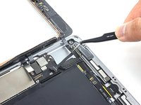
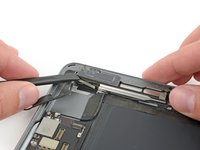
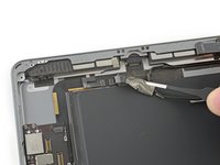
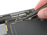
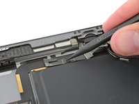
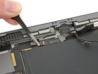
While supporting the digitizer, slide an opening pick between the two display cables to separate the last of the adhesive.
-
-
-
Remove the four Phillips #00 4.3 mm screws securing the LCD.
Both of the iPad 6th gen models i have seen so for (note they were cellular also) had the LCD secured with a grey silicone kind of adhesive in each corner under the screws. So you can’t just lift the LCD as you normally would after removing screws, it would break. I found you could pick at the corner closest to the rear camera easiest, slightly lift that corner and gently separate the other side next to the headphone jack. Then while supporting the LCD , lever the other end free with a up-and-down motion making slight progress each time.
On my iPad 6, there were small rubber tabs covering the two screws on the front camera side. I carefully held them out of place with tweezers while unscrewing the screws.
-
-
-
Use the flat end of a spudger to pry the LCD out of its recess just enough to grab it with your fingers. There may be glue around the screw holes that needs to be cut with a knife.
-
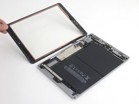
Flip the iPad LCD like a page in a book, lifting near the camera and turning it over the home button end of the rear case.
-
Lay the LCD on its face to allow access to the display cables.
When you replace the LCD be sure to make sure it is screwed in fully. It is easy not, especially on the cornet where the digitizer cables are. The LCD is very sensitive and if you bend it then it can stop working. I was just pressing the digitized in place at the end of a repair and the screen was covered in white lines.
I have no idea of what the logic board looks like !!!
-
-
-
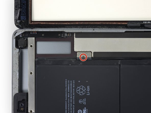
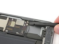
Remove the single 2.3 mm Phillips #000 screw securing the battery connector to the logic board.
-
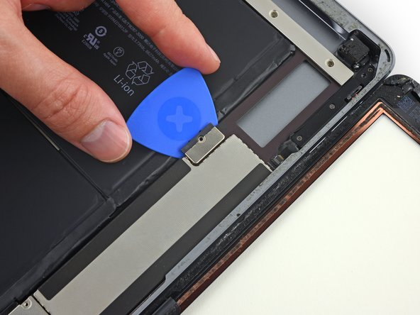
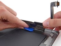
Slide the battery blocker underneath the logic board's battery connector at a 35 degree angle.
-
Leave the battery blocker in place as you work.
If you insert a regular pick without a gap then you can damage this connector and will need a new motherboard. If in doubt just insert into the left corner enough to raise it a tiny bit. Arguably, if you are not sure, then it is safer just power off and don’t power back on until everything is fully connected. A photo of how this connector looks with its cover off would really help for people that have not seen this type of battery connector before. You just need to get it to lift a tiny bit, Do not try to slide anything under the contacts….
I bumped this darn thing several times, it was twisted and skewed making me freak out but the iPad still works. I am thinking you should pull it out and put the screw back in right after the LCD is removed. Then use it again just before putting the LCD screen back in. The pick is sticking out there waitng to be be bumped.
Hi Robin,
Unfortunately, there is no easy way to pull the battery connector out of the logic board. If you try to pry this connector off, you will irreparably damage it. The easiest solution is to insert the battery blocker in-between to cut the power.
The battery isolation pick or battery blocker is an outdated way of isolating the battery, as you risk damaging the battery pins underneath the logic board.
So what is the new method?
This is my question as well. Seems like this phrase contradicts the instructions. Confusing. Any reply?
We are currently working on a better isolation procedure! In the meantime, I’ve updated the warning to hopefully clarify the issue.
Why do you need to “To reduce the risk of a short”? There does not seem to by any risk of a “short” in this process. I can see other reasons for disconnecting the battery. I am an electrical engineer so I would appreciate a professional grade answer to this question.
I’ll give it a shot!
When you remove the screw, it doesn’t disconnect the battery, as the connector uses spring contacts to touch the battery pads.
If you leave the battery connected, it leaves the logic board energized. As there are many exposed traces and SMT components on the logic board, there is a chance that you accidentally bridge a trace with a metal tool, resulting damage. In addition, the display connector contains tiny pins, and the pinout is such that if you pry the connector from an energized logic board, there is a chance that a voltage rail pin may accidentally touch something it shouldn’t, blowing out the backlight circuitry.
My battery was dead when i did the repair. Did not really need to perform this step
Take a waterproof playing card, cut out the shape of the battery blocker and slide that under. Battery blocked and pins not at risk of damage. Got that from a YouTube video made by a microsolder repair tech fixing the damage caused by jamming a blocker in between the contacts.
Thanks for the tip Melody! I’ve updated the instructions to include the playing card method.
I could not for the life of me get the playing card in there, but my iPad was turned off, so I decided to ‘risk’ a short, instead of potentially damaging the battery connectors by jamming the card in there as hard as possible. My repair went fine, no short, however I realized AFTER closing everything up that I forgot to put the battery screw back in. Really hoping this doesn’t become an issue long term, because I don’t want to pry this brand new screen off just to put the battery in.
Let us know! I wasn't able to use the screw again after removing the battery blocker. Now my iPad turns off and on every so many minutes and when it restarts it's 1% and then shows actual charge.
When you come to screw this back together, do not overestimate how little force it takes to strip the thread on this #000 screw. I did, and I now I can't screw this back down and have the problem where the iPad restarts every 3 mins 20 sec after you turn it on due to a poor connection here. I've used card to pack this out so the LCD puts a little clamping force on the terminal once you screw it back in, but it's not really enough so the iPad still suddenly restarts occasionally.
I use a small screwdriver and pry underneath that brown bracket from the top edge by the camera (with the elongated metal cover removed of course) all the way before the battery, then lift up just enough for me to unhinged the battery out of the secure post. I don't know why Apple has to go through ALL THIS just to connect the battery since there is a small screw AND ADHESIVE securing it anyway. Nonetheless the whole job (replacing the lcd screen and battery was a major pain in the neck!
-
-
-
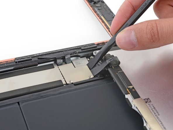
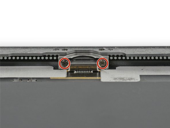
Remove the three 1.4 mm Phillips #000 screws from the display cable bracket.
I believe these are also Phillips #00, not Phillips #000.
I lost a 1.4mm screw where can I buy these small screws and how big are they? 1.4mm x? flared or flat head
-
-
-
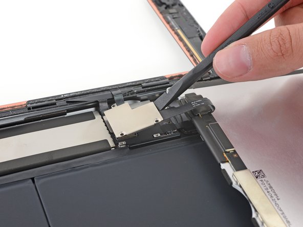
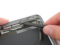
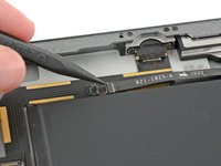
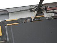
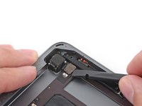
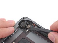
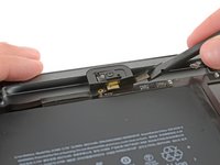
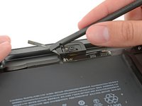
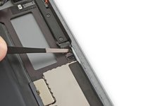
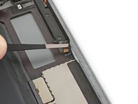
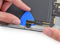
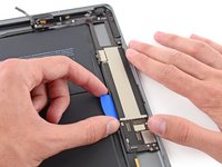
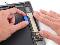
Use the flat end of a spudger to flip the tab on the home button ribbon cable ZIF connector upward.
-
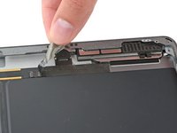
Carefully pull the home button ribbon cable straight out of the ZIF connector.
I'm confused about the home flex cable connector required for the 6th generation iPad. It was my understanding that this model required an 18 pin connector. But these excellent pictures clearly show a 14 pin connector, just like the one for the first generation iPad Air AKA the iPad 5. I know this is not the primary focus of this guide, but can anyone clarify this for me?
I did the whole repair but this part is the problem HELP !!! I unlocked it but it took me 1 hour to carefully pull out the HOME BUTTON RIBBON CABLE. It finally came out with tweezers but now I CAN'T GET IT BACK IN and as a result my touch I.D. won't activate. It seems there was a tiny bit of black tape overlapping the connector on the ribbon which I carefully cut off exposing only the connector on the ribbon itself but how the heck does it slide in before you lock it. It seems easy on Youtube videos but mine just doesn't slide in with hand or with tweezers. OR in fact is there another connector that controls the TOUCH I.D. ???
Failed this step- broke the connector. If I try this again, I'd be inclined try to remove the home button from the front panel without unplugging it. Everything else seems to work fine.
I too failed this step. Needed some up close pics of how this works. Now what do I do the connector on the board is broken?
-
-
-
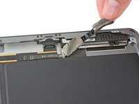
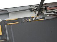
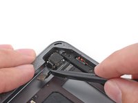
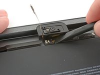
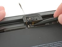
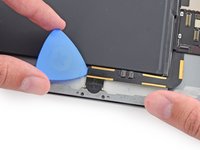
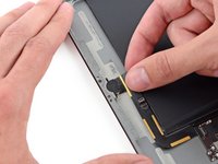
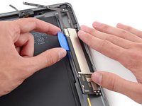
Use a the flat end of a spudger or a fingernail to carefully pop the two digitizer cable connectors straight up from their sockets.
Where can I get a good used motherboard for a A1954 iPad 6 gen everywhere I look, there sold out ?...
-
-
-
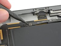
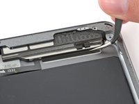
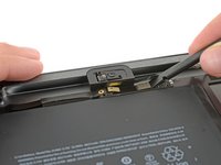
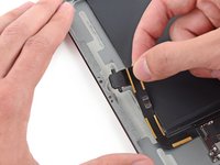
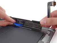
Carefully peel the home button ribbon cable up off of the adhesive holding it to the rear case.
If you can make sure to not pull on the home button side, i would leave out this step. i replaced two displays so far, on the first i removed it, but left it connected on the second attempt. worked like a charm
-
-
Tool used on this step:Polyimide Tape$9.99
-
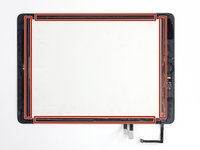
Remove the front panel assembly.
-
If you experience "ghost" or "phantom" touch input issues with your new display, this can be resolved by adding a layer of very thin insulating tape, such as Kapton (polyimide) tape, to the highlighted areas on the back of the panel. iFixit panels come with the proper insulation, and should not require the addition of any tape.
-
-
-
Insert a spudger under the antenna cable closest to the edge of the iPad and lift upward to disconnect the antenna cable connector.
Skip to the step 98 or even 100 if you just need to replace the power button - I think you should even consider this to replace volume buttons. I am fixing mine right now and screwed up the speaker cable. I did follow the instruction but totally missed the cable right below the tape. I proceeded further, but I just realized I didn't have to go through all the troubles. I wish ifixit.com can manage this type of direction clearly so that dis-assembly is minimum.
After you replace the Digitizer if you are getting random key presses it is likely to be because Kapton tape has not been applied to the edges of the digitizer. You need to cover the silver strip around the edge of the digitizer with kapton tape before reassembling. Works every time.
This is my first ipad and when the battery dies, it will be my last, way overrated and no options like memory cards or mini usb ports, and the battery thing is ridiculous,I wish I would have never bought this knowing this stuff , and way over priced.
It always helps to Google something before buying it. "iPad Air reviews" in Google would have saved you. I just find it funny how in this day and age, people STILL make "purchase mistakes" because they didn't take the time to research the several-hundred-dollar device they are about to commit to purchasing. You should have seen the amounts of research I did before buying my $1,399 Asus G751JY laptop. I'm absolutely pleased with it and am happy I don't deal with issues other people have. Just be weary, buddy. ALWAYS GOOGLE.
Scott S -
If you just want to replace the battery, skip to step 99. You can easily get to most sides of the battery without removing all other components. It worked for me. Good luck!
I wish I read this comment. Would have saved me a lot of time.
leo -
I followed your piece of advice and went to step 99. My new battery works just fine without removing all those components including the logic board - thanks a lot!!
An important note - as per the comments lower down, you can skip ahead to step 95 (unsticking the battery) just fine if you're just changing the battery, but after you've unstuck the battery you will need to go back to step 88 and soften the logic board adhesive so you can pry it up about a cm and lift the battery terminal up and over the post to remove it. I didn't realise the post was there, and broke off a piece of the original battery terminal that got stuck under the logic board. This prevented a good connection with the new battery, and caused random restarts after I put everything back together until I realised and went back to recover it.
Don’t skip to 99 because you need to remove the logic board.
I have successfully replaced the Battery without removing any components other than the Screen Assembly and LCD. You can skip steps 44 thru 99 by using a spudger as a wedge to lift & hold the Logic Board high enough to lift the battery contact over the post that holds it in place… this will save you a lot of time and frustration and makes the repair sooo much easier.
My goal was to replace the battery. As some suggested I skipped some steps. I did Step 46 and left out 47 to 100. But I think Step 46 can be skipped too. iFixit probably does not recommend skipping these steps because it is riskier to bend the batteries and damage them. But if you work carefully enough and make sure the adhesive has been softened well, you should be fine. It was no problem for me. It saved me quite some time. (I will write a comment in Step 102 to help you get the batteries out without Steps 46-100.)
-
-
-
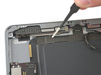
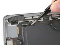
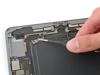
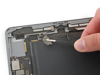
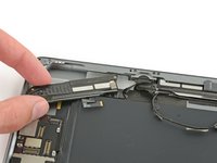
There are two large pieces of tape wrapped around the right antenna cable, securing it to the rear case.
-
Peel the tape up from the rear case.
You may partially skip steps 46 to 100, as it is not really mandatory to remove all those parts in order to remove the logic board and the battery.
-
-
-
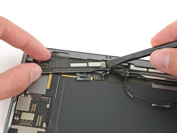
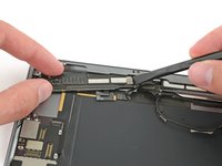
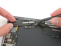
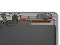
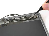
Carefully insert an opening pick between the speaker enclosure and the antenna cable bracket.
-
Slide the pick toward the home button to cut the adhesive.
-
Push the bracket away from the speaker until it clears the tape underneath.
The pick was not thin enough but the razor worked.
In my view there is a few destructive steps here. I have been able to remove this entire assembly by lifting only the adhesive tape anchoring it to the back without touching this fine metal bracket as touched in in Step 46 & 63 or tearing the foam in Steps 48 & 65 on both the left & right sides. Remove the screws as in Step 47 & 57 and the one’s either side of the charging port in 64 & 71. Once removed, the only thing securing these to the rear is adhesive tape. Lift the tape and walk the units out by nudging them from side to side.
Thanks. Made the whole next chunk much simpler :)
-
-
-
Remove the following Phillips #000 screws securing the right antenna:
-
One 2.3 mm screw
-
Two 1.4 mm screws
I would strongly advise not to follow this step and following ones: removing the 2 Wi-Fi antennas is not required for complete disassembly of the motherboard and battery, and you may potentially destroy your antennas: I scrupulously and foolishly followed this tutorial step by step and now I have severe Wi-Fi problems on my iPad because one of the 2 antennas has been damaged during the process (and by reading all the comments on this page you'll see that I'm not the only one to have this issue...).
=> As someone else already mentioned it in the comments, just skip most of these steps and go directly to something like step 79.
-
-
-
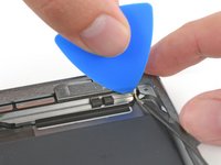
Insert the flat end of a spudger between the antenna and the speaker assembly.
-
Slide the spudger toward the home button to cut the foam adhesive securing the antenna.
Este paso es innecesario, ya que con solo quitar los tornillos es suficiente, no hace falta despegar la goma espuma que mantiene la antena de la bocina.
tout a fais il n'est pas nécessaire de décoller l'antenne du haut-parleur ! Il faut juste enlever les vis et continuer le démontage du haut-parleur en laissent l'antenne fixer a lui !!!
Faire de même pour le deuxième haut-parleur !
-
-
-
Insert a spudger under the left antenna cable and lift upward to disconnect the antenna cable connector.
-
-
-
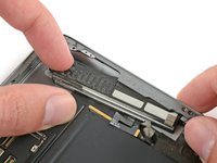
There are five pieces of tape wrapped around the left antenna cable covering the right speaker cable connector.
-
Peel the tape up from the rear case.
-
Fold the antenna cable out of the way.
This step was not very well explained. It fails to mention the speaker cable attached on to the tape. This caused the speaker cable to be torn since it is so thoroughly attached to the tape. Guide made no mention that it was under there or that you should be careful about it. Not even the usual remove the tape gently they just tell you to rip it right off no problem. Not sure how this was missed when the guide was so thorough about this beforehand.
Approx. 3/4 of an inch past the bend in the cabling underneath the tape lies the right speaker cable. Beyond this point proceed with extreme caution. Delicate cables and ZIF connectors underneath the tape will be torn or damaged if they aren't separated from the underside of the insulation tape first. Use fingernails or thin-edged tools.
An update to this would be nice. Will the Ipad work with a broken spaker cable? Is it possible to get replacement part? Maybe this step should be rewritten.
-
-
-
Use a spudger to help pull the speaker out from under the edge of the rear case.
-
Remove the right speaker from the iPad.
When did you remove the blocker after installing the battery blocker? No photos with blockers after this procedure.
-
-
-
Remove the three 1.4 mm Phillips #000 screws securing the upper component cable bracket.
-
-
-
There are two remaining pieces of tape securing the left antenna cable to the rear case.
-
Peel the tape up from the rear case.
-
-
-
Remove the following Phillips #000 screws:
-
Two 1.4 mm screws
-
One 2.3 mm screw
I didn’t need to take the left antenna and speaker out. If you just get the wire and tape out of the way so you can unplug the speaker flex cables and take out the lightning connector, then you should still be able to get the logic board out. the left speaker isn’t in the way at all.
-
-
-
Insert the flat end of a spudger between the antenna and the speaker assembly.
-
Slide the spudger toward the home button to cut the foam adhesive securing the antenna.
Este paso es innecesario, ya que con solo quitar los tornillos es suficiente, no hace falta despegar la goma espuma que mantiene la antena de la bocina
-
-
-
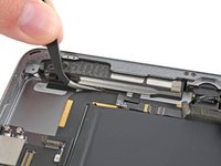
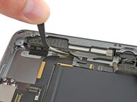
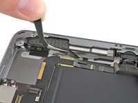
Use the flat end of a spudger to disconnect the headphone jack connector from the logic board.
-
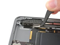
Fold the headphone jack cable out of the way.
Note for others. On this connector, i have some tape keeping it down, it's rather difficult to remove without ripping it. So i ripped the tape to remove it.
"Ripping" the tape seems ill-advised. A sharp ceramic craft paper cutting knife or the very tip of a fine-tip Exacto blade work well. Once the tape is cut on one side, the blade slides through it like it's nothing. Zero force required.
Be careful not to insert a blade too far or it may come into contact with conductive components.
-
-
-
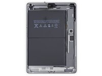
Remove the two 3.3 mm Phillips #000 screws securing the Lightning port.
NOTE for others who might miss this: this picture is looking down, out the bottom of the iPad. There are four other screws near the lightning port, two for the speakers and two for the port. You see these four easily, looking down at the battery and motherboard. These two are additional to those, and perpendicular to them. Both pairs of lightning port screws, one set perpendicular to the other, must be removed.
Where did the battery blocker go? It was introduced in step 35. Nowhere has it been said it can be removed . . . yet it is now absent in this picture. I took it out when I got to steps 93-96.
Yes this is a deceptive image as the battery and connector strap seem to be missing. Hold your iPad vertically and look down at the lightning port and you’ll see these hidden screws.
Thanks for your comment! I’ll add a note in the step.
-
-
-
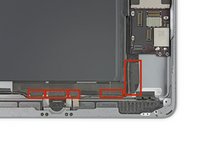
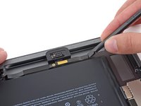
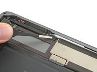
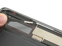
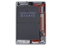
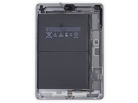
The adhesive is in the form of six pieces of black foam tape—refer to this step as you work at heating and prying to keep track of where each piece is located.
Thread a piece of dental floss under the tip of the logic board. Be careful when rounding the corner not to snag any ribbon cables. This easily released the foam tape up to the battery connector.
Les 2 images suivantes sont contradictoires. elles donnent l'impression de devoir enlever la carte mère.
@totoy Effectivement, cela peut-être perturbant, mais ces images servent de référence et expliquent où se trouvent les six morceaux d'adhésif qu'il va falloir décoller au cours des étapes suivantes pour retirer la carte mère.
-
-
-
Finally, slide the opening pick between the battery and the Lightning connector itself to separate the last of the adhesive underneath the cable.
There are two screws holding the lightning connector to the rear case, I didn’t see them in this guide. I recommend removing them before you attempt to remove the lightning connector, otherwise you’ll look like an idiot struggling with it for around 1/2 an hour like I just did.
Did you skip this step?
I had this problem too!!
Will Young is correct. The two extra screws are horizontal - they are in addition to the vertical screws mentioned in step 82.
@usablethought AFAIK there are only two screws securing the actual port to the chassis. You can tell by looking at the part—there are only two screw holes. Those additional screws can be left in place, as shown in the photos. At least, that was my experience. If you’re working on a different model, then of course you may need to improvise—the instructions are only for the model indicated.
-
-
-
Pull the Lightning connector straight out of its recess in the rear case.
there were two screws holding the lightening connector in place on my iPad
Yep! In this guide those screws are removed in Step 82, but you can remove them at any point prior to taking out the Lightning connector.
CAUTION - there are two ‘hidden’ screws holding the lightning port that face the battery. Hold the iPad vertically and look down to see them. I almost broke the cable trying to remove it thinking it was just stubborn adhesive. Yes its mentioned at Step 82 but its a confusing illustration and easily overlooked.
-
-
-
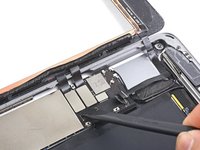
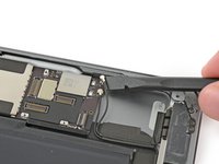
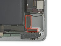
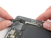
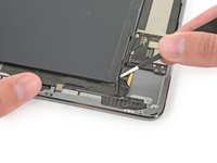
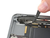
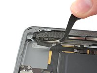
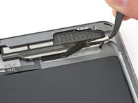
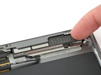
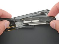
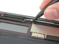
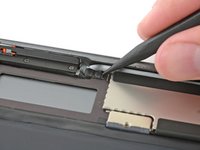
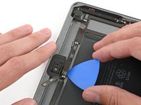
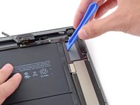
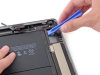
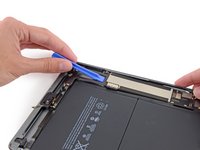
Insert a plastic opening tool in the rectangular gap in the upper area of the logic board, and pry the logic board up from the rear case.
-
While keeping the opening tool underneath the logic board, slide it down the length of the gap to free the upper end of the logic board from the adhesive.
-
-
-
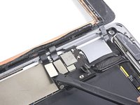
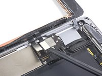
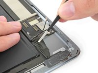
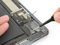
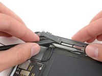
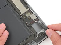
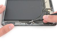
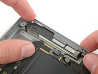
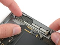
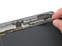
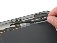
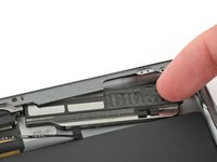
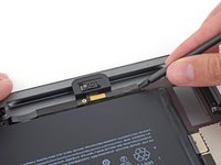
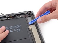
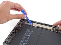
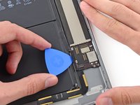
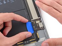
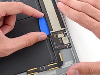
Slide the pick up the length of the logic board.
-
Once the adhesive has been cut, pry the battery side of the logic board upward off of the rear case.
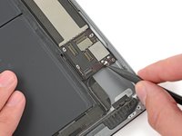
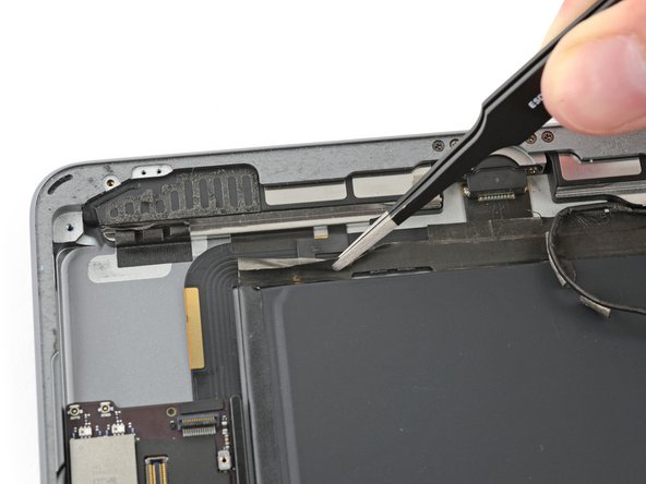
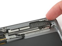
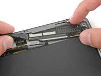
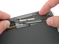
Don't touch the small components which are under the motherboard !!! If you do it your iPad is definitively dead.
-
-
-
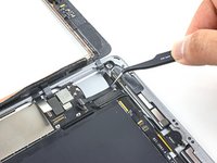
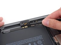
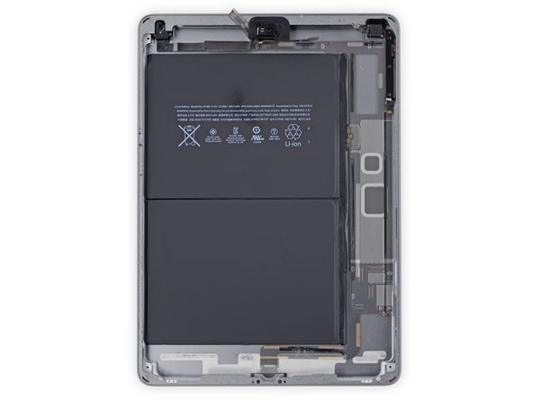
Remove the logic board from the iPad.
Nice guide, thank you, very helpful. There would be no way to guess where the glue stripes are located and a couple of connectors are very difficult to spot. I don't see any need to remove the antennas and the speakers though, they are not really an obstacle to remove the board and can be left in place. The lightning connector is secured in place by two other two horizontal screws which are not shown in the guide.
Thanks again !
Technically, you are correct. But those screws are holding a bracket-like piece for the lightning connecter to screw into- which if you think about it, it wouldn't be considered apart of the lightning port (or at least that's what i think). Not trying to start an argument, as this comment is old, but yeah.
Kaz -
This is a bear of a job, and I wouldn’t have had any hope of completing it without this guide. THANK YOU for all your hard work!!!!
-


To reassemble your device, follow these instructions in reverse order.
To reassemble your device, follow these instructions in reverse order.
Cancel: I did not complete this guide.
11 other people completed this guide.


2 Comments
where can I buy a logic board?
I needed to replace the charger port for an iPad 6. This guide, plus a youtube vid on how to replace the charger port helped me achieve this last night.
Thanks for the detailed instructions!!!