Introduction
This is a short video on how it should look like when you take it apart
Video Overview
-
-
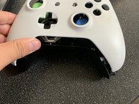
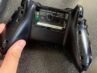
First take off the back two pieces, you might need something to stick in in order to pop them out
-
-
-
-
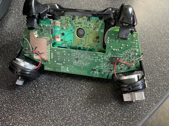
The Triggers use Linear Hall Sensors now, U10 (RT) and U11 (LT). They have 3 pins, 1 - VDD (power), 2 - Output, 3 - VSS (ground). The VDD for them comes from U9, which is turned on/off by U1 at 125Hz, 8ms period, On ~1.4ms, Off ~6.6ms (~18% Duty Cycle). This is done mainly to save power.
-
-
-
The Power board has 3 parts U1 is for when the USB cable is attached, it takes the 5v and knocks it down to ~3v for the other two circuits. U2 is for a 3.5v source that powers the LED, IR LEDs and the Rumble motors. It's TP7 on the MCU board. U3 is for the 3.3v source that powers pretty much everything on the MCU board. It's TP9 on the MCU board.
-


2 Comments
A lot of help, thanks. I got an elite 2 so figured if see whats inside my stock boy
Well, I was looking for an actual teardown, but it just stops after taking the outer shell off and just talks about some of the internals. Needed the instructions for a full teardown to fix face buttons.