
Introduction to Capacitors
Here is a bit of the dry stuff, just to help understanding what a capacitor is and generally does. A capacitor is a small (most of the time) electrical/electronics component on most circuit boards that can perform various functions. When a capacitor is placed in a circuit with an active current, electrons from the negative side build up on the closest plate. The negative flows to the positive—that is why the negative is the active lead, although many capacitors are not polarized. Once the plate can no longer hold them, they are forced past the dielectric and onto the other plate, thus displacing the electrons back into the circuit. This is called the discharge. Electrical components are very sensitive to voltage swings, and as such a power spike can kill those expensive parts. Capacitors condition DC voltage to other components and thus provide a steady power supply. AC current is rectified by diodes, so instead of AC, there are pulses of DC from zero volts to peak. When a capacitor from the power line is connected to ground and the DC will not pass, but as the pulse fills up the cap, it reduces the current flow and the effective voltage. While the feed voltage goes down to zero, the capacitor begins to leak out its contents, this will smooth the output voltage and current. Therefore a capacitor is placed inline to a component, allowing for absorption of spikes and supplementing valleys, this, in turn, keeps a constant power supply to the component.
There is a multitude of different types of capacitors. They are often used differently in circuits. The all too familiar round tin can style capacitors are usually electrolytic capacitors. They are made with one or two sheets of metal, separated by a dielectric. The dielectric can be air (simplest capacitor) or other non-conductive materials. The metal plate foils, separated by the dielectric, are then rolled up similar to a Fruit Roll-up, and placed into the can. These work great for bulk filtering, but they are not very efficient at high frequencies.

Here is a capacitor that some may still remember from the old radio days. It is a multi-section can capacitor. This particular one is a quad(4) section capacitor. All that means is, that there are four separate capacitors, with different values, contained in one can.

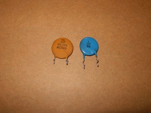
Ceramic disc capacitors are ideal for higher frequencies but are not good to do bulk filtering because ceramic disc capacitors get too big in size for higher values of capacitance. In circuits where it is vital to keep a voltage source stable, there is usually a large electrolytic capacitor in parallel with a ceramic disc capacitor. The electrolytic will do most of the work, whereas the small ceramic disc capacitor will filter off the high frequency that the big electrolytic capacitor misses.
Then there are tantalum capacitors. These are small, but have a greater capacitance in relation to their size than ceramic disk capacitors. These are more costly, but find plenty of use on the circuit boards of small electronic devices.

Although non-polar, old paper capacitors had black bands at one end. The black band indicated which end of the paper capacitor had some metal foil (which acted as a shield). The end with the metal foil was connected to the ground (or lowest voltage). The main purpose of the foil shield was to make the paper capacitor last longer.

Here is the one that we are most likely interested in the most, when it comes to iDevices. These are very small in comparison to the before listed capacitors. They are the Surface Mount Device (SMD) caps. Even so they are miniature in size compared to the previous capacitors, the function is still the same. One of the importance, besides the values of these capacitors, is their "package". There is a standardization for the size of these components, i.e. package 0201 - 0.6 mm x 0.3 mm (0.02" x 0.01"). The package size for the ceramic SMD capacitors follows the same package for SMD resistors. This makes it almost impossible to determine if it is a capacitor or a resistor by visualization. Here is a good description of the individual size based on package numbers.

SMDs on a PCB

Large SMDs
Testing Capacitors
Determining the value a capacitor has can be accomplished in a few ways. Number one, of course, is a marking on the capacitor itself.

This particular capacitor has a capacitance of 220μF (micro farad) with a tolerance of 20%. This means that is could be anywhere between 176μF and 264μF. It has a voltage rating of 160V. The arrangement of the leads all show that it is a radial capacitor. Both leads exit on one side versus an axial arrangement where one lead exits from either side of the capacitors body. Also, the arrowed stripe on the side of the capacitor indicates the polarity, the arrows are pointing towards the negative pin.
Now the main question here is, how to check a capacitor to see if it needs replacing.
To perform a check on a capacitor while it is still installed in a circuit, an ESR meter will be necessary. If the capacitor is removed from the circuit then a multimeter set as an ohm meter can be used, but only to perform an all-or-nothing test. This test will only show if the capacitor is completely dead, or not. It will not determine if the capacitor is in good or poor condition. To determine if a capacitor is functioning at the right value (capacitance), a capacitor tester will be necessary. Of course, this also holds true to determine the value of an unknown capacitor.
The meter used for this Wiki is the cheapest one available at any department store. For these test it is also advisable to use an analog multimeter. It will show the movement in a more visual way than a digital multimeter that only displays rapidly changing numbers. This should enable anybody to perform these tests without spending a fortune on something like a Fluke meter.
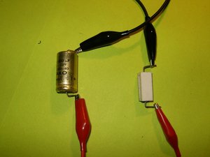
Always discharge a capacitor before testing it, it will be a shocking surprise if this does not get done. Very small capacitors can be discharged by bridging both leads with a screw driver. A better way of doing it would be by discharging the capacitor through a load. In this case alligator cables and a resistor will accomplish this. Here is a great site showing how to construct a discharge tools.
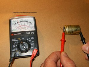
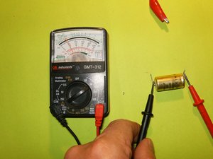
To test the capacitor with a multimeter, set the meter to read in the high ohms range, somewhere above 10k and 1m ohms. Touch the meter leads to the corresponding leads on the capacitor, red to positive and black to negative. The meter should start at zero and then moving slowly toward infinity. This means that the capacitor is in working condition. If the meter stays at zero, the capacitor is not charging through the battery of the meter, meaning it is not working.
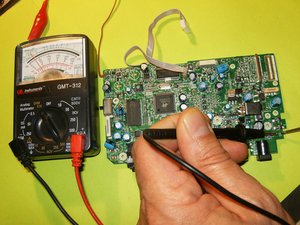
This will also work with SMD caps. Same test with the needle of the multimeter moving slowly in the same direction.
One more test that one can do on a capacitor is a voltage test. We know that capacitors store a potential difference of charges across their plate, those are voltages. A capacitor has an anode which has a positive voltage and a cathode which has a negative voltage. One way to check if a capacitor is working is to charge it up with a voltage and then read the voltage across the anode and cathode. For this it is necessary to charge the capacitor with voltage, and to apply a DC voltage to the capacitor leads. In this case polarity is very important. If this capacitor has a positive and negative lead, it is a polarized capacitors (electrolytic capacitors). Positive voltage will go to the anode, and negative goes to the cathode of the capacitor. Remember to check the markings on the capacitor to be tested. Then apply a voltage, which should be less than the voltage the capacitor is rated for, for a few seconds. In this example the 160V capacitor will be charged with a 9V DC battery for a few seconds.

After the charge is finished, disconnect the battery from the capacitor. Use the multimeter and read the voltage on the capacitor leads. The voltage should read near 9 volts. The voltage will discharge rapidly to 0V because the capacitor is discharging through the multimeter. If the capacitor will not retain that voltage, it is defective and should be replaced.
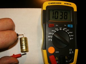
The easiest of course will be to check a capacitor with a capacitance meter. Here is a FRAKO axial GPF 1000μF 40V with a 5% tolerance. Checking this capacitor with a capacitance meter is straight forward. On these capacitors, the positive lead is marked. Attach the positive (red) lead from the meter to that and the negative (black) to the opposite. This capacitor shows 1038μF, clearly within its tolerance.
To test an SMD capacitor may be difficult to do with the bulky probes. One can either solder needles to the end of those probes, or invest in some smart tweezers. The preferred way would be using smart tweezers.

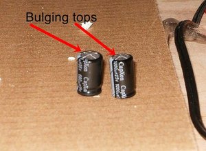
Some capacitors do not require any test to determine failure. If a visual inspection of the capacitors reveal any sign of bulging tops, those need to be replaced. This is the most common failure in power supplies. When replacing a capacitor, it is of utmost importance to replace it with a capacitor of the same, or higher value. Never substitute with a capacitor of lesser value.
If the capacitor that is going to be replaced or checked, does not have any markings on it, a schematic will be necessary. The image below from here shows a few symbols for capacitors that are used on a schematic.

This excerpt from an iPhone schematic indicates the symbol for capacitors as well as the values for those capacitors.

This Wiki is pretty much just the basics about what to look for on a capacitor, it is in no way complete. To learn more about any of the common electronic components, there is a plethora of good on and offline course available.
Popular Capacitor Vendors

Team

49 Comments
Thank you for the good info.
Ivo Tanev - Reply
You have explained capacitors in a way that a person with very basic electrical knowledge (such as myself) can understand. I read your information from beginning to end. Thank you for sharing.
lisacarroll57 - Reply
Thanks for the precise and easy to Understand information on Capacitors. Well done!
sanjaycolaco - Reply
Great explanation! I think you should also mention the use of capacitors as coupling capacitors, to block any DC while letting the AC (audio) signal through. Many DIY-ers work on guitar effect pedals, where one should always use coupling capacitors on both input and output jacks to ensure no DC can flow from the effect circuit to the instrument, or the amp.
joakimgrahl - Reply
Right on. Thats how I ended up here.
mogwaiemperor -
@joakimk that is a great idea. I will expand on this is the near future. Currently working on resistors, diodes and fuses.
oldturkey03 - Reply
Great reading and learning.
lpmeter - Reply
One question...What if your Cap does not have a positive,or negative symbols,then how would you check the component?
lpmeter - Reply
If no ones answered your question yet, chances are its non-polarized, which just means it doesn't matter. Either lead could be negative or positive. If it is shaped like a little metal can (like the ones up there↑↑ in dudes story wth the bulging tops) just assume it is because they almost always are. Or if it's shaped like a little shiny colored test drop shape, which usually is still marked, if assume those are too to be safe . Those would be tantalum. Google what those look like and also silver mica caps. Never seen those before. But if its a little box shaped cap, or kinda boxy and orange or yellow or blue or gray, or looks painted up like some ocean fish, then it wont have a polarity . And neither will the little orangish beige tiny circular ones that are ceramic . But be sure first because the ones that do will blow the !&&* up, and catastrophically at that sometimes.
mogwaiemperor -
Thank you a million times AND Massively Big Hugs to you for saving me hundreds of dollars ... I have an Amana washer and one of the two capacitors was giving unusual readings as indicated in this "IFIXIT" manual, so I decided to re-solder the one that gave a strange reading and viola, it cured the problem immediately ... the thing that alerted me to a soldering issue was the dull colour of the solder on that one capacitor, whereas the other one had bright and shiny solder ... thank you a million times for all that you do to enlighten and educate the public and save us a few dollars ... Blessings be upon you and your kind heart ... 8)
James Nickerson - Reply
Thank you great explanation
dawit - Reply
frank ennbeans - Reply
I must say this was the first web lecture I enjoyed learning ...
Nitin Rathor - Reply
Nice keep it up
Abdoulie Bah - Reply
Very useful and simple explanation to understand and to save lot of money. Thank you
Sunil Manuweera - Reply
Thanks for the Information, Very useful and straight to the point, keep up the good work.
sibongeleni nxumalo - Reply
This is soo gooooooood!! Thank you! It`s so hard to find good learning material on this subject.
Lupas Florin - Reply
bravo sir i understand you make explan simple
princenovair - Reply
Thanks for that explanation
Joseph Ssemiyingo - Reply
Very helpful, thanks!
Jason Dunn - Reply
Very well explained info
thanks
SEUN SONOIKI - Reply
Thanks for the simple explanation!
Tech Sure - Reply
Thanks, for the very informative article!
JOHN AQUILINO - Reply
Umm the best capacitors are made by Panasonic and pretty much the standard and I wonder why that was not in the list of vendors.
Ravi Rajangam - Reply
Digikey, Mouser, etc. that are listed are distributors of electronic components. They sell brands like Panasonic. I am curious on what basis you consider Panasonic caps to be the best? For SMT caps, I would strongly disagree. For SMT-type caps, TDK, Murata, and even Samsung have the best technology… offer highest values/voltages/temp. coefficient in a given package size, more stable over life, better retain their value after being subjected to ESD, and tend to be able to take more stress without cracking/damage. For SMT chip resistors, I do agree that Panasonic is one of the top options. NOTE: This is my personal opinion and does not reflect the opinion of my employer.
matthewlasorsa -
This is a very explanatory write up... Very elementary and useful for all level of electronic understanding…thanks alot for this?.
Amusan Olamilekan - Reply
Hello!
Thanks for your detail explanation. I also have some questions which i have CBB22 in my hand in this company write 355j 400v.
I want to check is this mentioned volts are DC or AC. and how I measure the volts??
Mudassir Ghulam Kasbati - Reply
You are the tutor I need because You made it possible for a hard head like myself understand, thank you.
Angel Altavilla - Reply
Here is a very informative article about Electrical Bonding.. please follow it..
Electrical-Technology - Reply
Why cannot I measure capacitors in circuit using a multimeter with a capacitor measurement mode? I only need to check whether the capacitor is dead or not, no need for the exact capacitance value.
Jeri Haapavuo - Reply
Hi ihave a tv capacitor 450 volts 100uf.when tested it reads198uf would this be faulty? Would be greatfull if you could get back.
terry spencer - Reply
1000uf 50v electrolytic capacitor testing with esr reads 1940uf. This is a bad cap right? Thank you!
Mj Pags - Reply
Thank you, i have learnt something from your wiki.
dubemw - Reply
Thanks for your comprehensive article. It helped a great deal - my treadmill was moving erratically and after reading your article discovered that a large electrolytic capacitor was positively bulging at the top!
Charlieroy - Reply
Great explanation. I have learned electronics only for Physics in Advanced Level education (2 years in school just before entry to the university in Sri Lanka). But I clearly understood everything you have written and that is very much useful. Thank you !
kevinfer83 - Reply
Thanks for the explanation. Now, how about ceiling fan capacitors? Some have two capacitors and some have only one. Do you know why?
amlopex - Reply
Two smaller ones may be notably cheaper than a bigger one. I guess in a ceiling fan the product size is no problem and thus two may be used as well (taking a little bit more space).
Jeri Haapavuo -
Thanks that's great
Ya Max Joel KOUAKOU - Reply
Thanks for this! So if my multimeter has a “uf" setting, does that mean it can test capacitors?
T N - Reply
Most likely, yes… “µF” represents ‘microfarads’, and farads are a value of capacitance
matthewlasorsa -
Merci pour cette page ! Typo in French version à propos du condensateur de 220muF : ça devrait être entre 176 et 264, pas entre 176 et 064.
Cyprien Gay - Reply
Bonjour Cyprien ! Bien vu ! J’ai corrigé. Notre site est conçu comme un wiki modifiable par tout le monde. La prochaine fois, n’hésitez donc pas à corriger en cliquant sur Traduire en haut à droite :) Merci pour l’œil attentif et excellente journée à vous !
Claire Miesch -
thanks, easy to understand
Med Djihed - Reply
Very insightful and clear explanation, thank you very much.
[deleted] - Reply
Great general summary but I strongly disagree with the advice quoted below about using ‘higher capacitance values’. Replacement capacitors should ALWAYS be of the same nominal capacitance value as the original. Yes, there are cases where a circuit needs only a minimum capacitance to operate, so using a higher value would be ok. But there are many cases where a specific capacitance value is required for the circuit to operate correctly and safely. Don’t risk it. Use the same value, type (electrolytic, polar vs non-polar, etc.), and package size as the original.
It is acceptable to use a higher voltage rating or smaller tolerance value than the original if necessary. For SMD caps, using a higher class of dielectric can be acceptable (i.e., if original cap was ‘X7R’, a ‘C0G’ replacement should be acceptable).
matthewlasorsa - Reply
Thank u very much
DokMawuer - Reply
Awesome!
Great old dry stuff that never gets old.
And the pictures are the cherry on the circuit.
Your great work is much appreciated my friend
Tlze App - Reply
CORECHIPS is an industry-leading independent electronic components distributor with cost-saving and reliable supply chain ,serving global customers with one-stop sourcing solution, satisfying value-added options and setting up the long-term partnership with them.
zoe - Reply
Can I replace a 68uf 200v with a 120uf 200v
Reperofsouls - Reply