

Philips LCD no DC voltage in output
Hi guys,
I'm new in the forum and this is my first time I ask for some help in TV issues.
My PHILIPS 42PFL5604H / 12 after some minutes, it turn off instantly with a electrically pop sound comes from the rear.
Now, I uncover the back of the TV to check the power supply for bad capacitor, but there isn't no bulk capacitor. The fuse isn't broken, I check it with a tester.
Here, you can find a video of the problem:
https://drive.google.com/open?id=1F3Bddi...
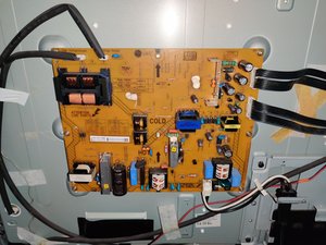
And, here a photo of the Power Supply (LGIT -> PLHL-T845A | PLHL-T813A):
https://drive.google.com/open?id=15cMC69...
Thanks to everyone for the help.
Update (05/24/2020)
When the TV was turned on, I shutdown it with the power button on the remote control, unplug the 2 cable from PSU to MainBoard, and test the two pin (Standb, 3V3Stdby.) The result is:
3V3Stdby -> 3.25 V in DC
Standb -> 2.63 V in DC

If the TV is power on, I can listen some noise from the Blue Transformer (INVERTER) that you can listen here:
Blue Inverter Noise: https://drive.google.com/open?id=1X3jbQI...
When the TV power off, it seems wants to turn on and the rear panel and the LED attached to the PSU board, blinking an flashing a couple of times, and after this no power goes to the Main Board.
A video of this behavior can be seen here: https://drive.google.com/open?id=1MVkILR...
I try to check, with Multimeter set to the Alternate Current Measure, the flow of current from the 244 Volts A/C Input. The big capacitor is ok, and I check also the bridge rectifier and also seems ok (when I checked it, the voltage in middle pin associated to alternate current is 244 V)
Update 2 (05/24/2020)
Due to strange measurement, I check the path that connect Standb and 3V3Stdby. I upload some images with some draw.
Rear PSU, Main Board connector part:

Front PSU, Main Board connector part:

Update (05/25/2020)
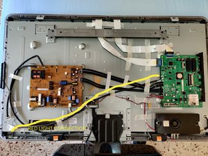
To better understading the connection between components, here you can see the photo of the back pannel of my TV.
The Red Light is connected to the Main Board. Sometimes it turning on, when I plug the A/C Input cable, some times not. When the A/C Input cable and no cable appear, the 3V3Stdby and Standb are equal to 0.0V. When it turn on, the values are:
3V3Stdby: 3.25
Standb: 2.65
This because, as @jayeff said in comments, “The two leads are connected to the same opto-coupler“, so the diode cause loss voltage between the two pins
Is this a good question?


8 Comments
@gianlucarbone as @jayeff already pointed out this does look/sound like a power board issue. I would try to remove the back cover from your TV (Keep your hands out of it) and turn it on. Then watch to the boards to find out if you see some spark or where the noise comes from. This does sound like a bad transformer. Also, consider removing the power board and take a look at the back side. Let's see if there are any marks etc. on it. Check around the bridge rectifier etc. Let us know what you find out.
by oldturkey03
@oldturkey03 I have done a video for check the connection in the back side of the power supply. I will post it in another answer. I need to use link of google drive because they are very huge videos in high quality to check the solder. About the transformer, I hear a little noise from the blue transformer and record in a audio file. I will post it also. Thanks for your help
by Gianluca Carbone
Hi @gianlucarbone ,
I assume you measured this when there was no red standby light, is this correct?
If so, it seems very strange to me that the 3V3 Stby voltage and the Standb voltage are not the same value.
2.63V is a very odd value to have for a reference voltage to be sent to the mainboard. If it were also 3.25V it would be more understandable.
Maybe you should follow the path back from the Standb connector and check what components are connected to it on the Power board. Just thinking that maybe the red light doesn't come on because the mainboard doesn't get the full voltage that it is expecting, but it may suddenly be there or it is building up perhaps and then the light turns on.
Even allowing for a 10% swing from the maybe expected 3V (this is a guess by me), for the Standby voltage, it is outside that range as well.
Just what I'm thinking about this
Cheers
by jayeff
Hi @jayeff. No, I measured it after waiting the red light turns on. This behavior is strange. I try to explain what I did.
First, I plug the cable to the wall socket;
Next i waiting for the Tv turn on yourself (I cannot do anything with remote control).
When for some reason the TV is turning on, a white led blinking and then I can see image and sound, normally.
After some minutes, it turns off. But, when is on I can press the red button in remote control and turn off the tv, and I can see the red light. So, what I have done is, (after turning off the tv from remote control), make me sure the red light is present, next I unplug the cable from the Main Board to make measurements, put the black cable of the multimeter in a metallic part of the TV, and with the red cable, measure the pin (using direct current obviously). Next, I can plug the cable to the main board and the red light is on, because the power supply "doesn't became faulty". I update my question with some images about the path of the pins
by Gianluca Carbone
@gianlucarbone ,
Do you mean that the red light stays on when the mainboard is disconnected from the power board when you measured the voltage? If so then it's getting a bit difficult, at least for me.
Really confusing as it seems that the two leads 3V3 and Standby are connected to the input of an opto-coupler
The two leads are connected to the same opto-coupler which separates the AC side from the DC side in the power board. That may explain the voltage difference because each lead goes back to a different point connected to the input of the opto-coupler i.e. 0.7V dropped across the diode - 3.25V -2.63V =0.62V which is close enough
So with the mainboard disconnected the voltage being seen must be coming from somewhere else in that part of the power board as the opto-coupler supplies no voltage to its' input side. The diode in the opto-coupler (really a LED) turns on its' associated transistor when current flows through the diode therefore presumably turning on (or off?) something else in the AC side of the board
by jayeff
Show 3 more comments