
Repair and support for ceiling-mounted bladed fans.

41 Questions View all

I am having trouble finding capacitor for Ceiling fan

I am having trouble finding capacitor for Ceiling fan. The spec my capacitor is :

450V.AC 50/60Hz, 1.25 + 1 + 1.5uF +/- 5%

What should I do ?

Update (05/16/24)

On the capacitor the following is also printed "CBB6-1" as well as "EN60252"

Update (05/16/24)

Here is a photo shot of the capacitor :

Block Image

Update (05/16/24)

It has 5 leads ==>

Block Image

Answer this question I have this problem too

Is this a good question?

Score 1
3 Comments

Hi @sdavis96819

What is the make and model number of the ceiling fan?

by

I am not sure I couldn't find those details on the fan

by

Sorry I found it "Electro Star Model Star 4 - 3 speed"

by

Add a comment

2 Answers

Most Helpful Answer

Hi @sdavis96819

I also couldn't find a replacement so if there is room in the fan you may wish to consider installing two capacitors instead. A 1.5µF + 1.2µF capacitor and a 1µF capacitor.

The 1.2µF capacitor is close enough in value to the 1.25µF given the 5% tolerance.

Also for the 1.5µF + 1.2µF + 3µF capacitor example linked above, if you do decide to use it, be sure to insulate the wire connected to the 3µF capacitor input side i.e. not the common output side, so that it won't cause any problems. Either that or cut it off.

Was this answer helpful?

Score 1

2 Comments:

If I used the "1.5µF + 1.2µF + 3µF" as well as the 1uF you suggested how would I wire it up ? If you can see in my 2nd photo my current capacitor has a Brown, purple & red wire as well as 2 gray wires !

by

@sdavis96819

Withe the 1.5µF + 1.2µF + 3µF capacitor the 2 greys are the common output so wire them to where the existing grey wires went.

Then wire in the the 1.5µF brown wire to where the existing brown wire went,

The 1.2µF red wire to where the existing red wire went.

Then insulate the purple 3µF wire so that it doesn't touch anything electrically. Don't cut it yet in case for some reason the wire colours don't match the usual way that they're connected inside the capacitor.

With the other 1µF capacitor you would wire 1 black wire to where the existing purple wire went and the other black wire where the grey wires are connected.

by

Add a comment

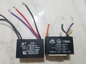
I found a Reddit thread talking about how to wire these up, and it included this picture.

Block Image

If yours follows the same layout, then it would correspond to the following connections.

1.25uF Red

1uF Purple

1.5uF Brown

Ground Grey / Grey

So the two grey wires are both grounds, and you can use one or both of them. Each of the three capacitors should be wired between the given colored wire and a ground. So if you buy three separate capacitors, you'd wire them to wherever the existing wires go as follows.

1.25uF Red to Grey

1uF Purple to Grey

1.5uF Brown to Grey

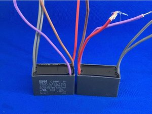
I ran across an eBay listing that's as close as anything I could find; it has two out of the three values you need.

CBB61 1.5UF+1UF+2UF 450 V AC Small Generator Capacitor 50/60Hz - eBay

Block Image

This one is really scrambled according to the colors. Here's how you'd wire it

1.5uF Red to existing Brown

1uF Brown to existing Purple

Gray to Gray / Gray to Gray

Then you'd still need a separate 1.25 to go to the existing Red / Grey connections.

Sheesh, be nice if this stuff had some kind of standardization, right?

Was this answer helpful?

Score 1

7 Comments:

Thank you so much for this explanation but what should I do - there appears to be a contradiction between these color coding ! ? What will happen if the color coding of my cap and thus my writing is wrong ?

Also I AM thinking of buying individual caps - if I get slightly higher (within 5%) will my fan spin faster ?

by

@sdavis96819 Color coding isn't standardized; any manufacturer is free to use any color they want on any wire they want, so you really have to go by the wiring diagrams and not depend on the colors of the wires, which is what I did when telling you which color wire goes where.

Tolerances are specified as a range of allowed values for a particular component, so if you find a replacement part that is within that 5% tolerance range, then it will work correctly. I doubt you would notice a 5% difference in the fan speed, which is all you would see.

by

But unfortunately there is no wiring diagram on my capacitor ?

by

@sdavis96819

Most DMM (digital multimeters) have a capacitance test function.

Some can test up to 20µF.

If you have a DMM check if it has this function and to what value it can test and then use that to check which lead belongs to which capacitor. If there are 5 leads then the 3 different coloured leads are individual to each of the 3 capacitors and the other two (same colour) are common to al i.e. 3 separate inputs and 2 common outputs.

If you have a DMM that doesn't have a capacitance test then here's a link that shows how you can work out the value of each capacitor so that you know which lead is appropriate to which capacitor if there are 3 mounted in the same package.

How did you know that the original capacitors that you want to replace are bad? Did you test all of them?

by

Can I check the capacitors with a DMM while it still connected to the fan ?

The fan was running slow and it appeared from my research that people had suggested that the capacitor was the first thing to check \ replace for slow fans. Is there someway to check the cap before I disconnect it to see if it is bad and the cause of the slowness of the fan ?

by

Show 2 more comments

Add a comment

Add your answer

Sdavis will be eternally grateful.
View Statistics:

Past 24 Hours: 1

Past 7 Days: 8

Past 30 Days: 93

All Time: 93