
Beats Pill Plus USB lightning charging port

Hi

Not sure if anyone can help me but I have attempted my first ever soldering after buying all the stuff required but I have an issue and hopefully someone can help .

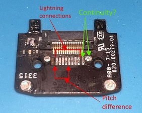
I have a dr Dre beats pill plus that has a damaged lightning charger . I purchased the part from America and have managed to remove the old one and was quite chuffed with myself till I noticed under the scope that one of the traces are still attached to the old charging port . My question is can I leave it and re solder the new one on or do I have to reattach or repair the trace?

I have attached photos if someone can help . The one I’m referring to is the light blue background where you can see the missing trace on the left hand side of the pins

Thanks

Block Image
Answer this question I have this problem too

Is this a good question?

Score 1
Add a comment

2 Answers

This is the bad part right? The one you are replacing. If this is the new part then you’ll need to get another as without the trace you have no means of attaching the other part.

Was this answer helpful?

Score 0

1 Comment:

Hi this is the part that has to go back on another board and is the original part minus the charging port that I removed and unfortunately the trace came with it that’s missing on the left .

The lightning connector has 8 pins where this part has 10 traces so I was curious as to what the traces lead to or if they were ground . I have decided to replace the trace now and see how that goes . Thanks for your response

by

Add a comment

@haswelladrian let's see the connector you took of or your new one. also, Take another picture of your board, just take it straight down so we can look directly from the top down (none of that slight angle view ;-) The lightning connector is commonly a 8 pin connector and on your board it looks like you still have all 8 solder pads. Right now, it looks like the torn pad is part of the anchor for the connector. If so you can solder the new one in place with rebuilding the missing pad.

Update 01/05/25

@haswelladrian dang, that is a lot of money for parts. If this would be my device, I would first check to see if the out solder pads are anchor points only. I believe it is so because of the difference in pitch on the pads. Then I would check the opposite side to verify that it is ground. I would use a multimeter and check for continuity between the opposite pad and ground. If there is continuity, then it is safe to assume it is indeed ground (anchor point) I'd proceed to solder the new connector on. Then verify it's function. If it does work, then I'd apply some hot glue on the side of the connector where the solder pad is missing. That will add some stability.

Rebuilding the torn solder pad may actually be a challenge if you can't see the trace where it connects to. Some are easier to fix than others. I'll add some pictures to explain what I am referring too.

Block Image

Was this answer helpful?

Score 0

8 Comments:

Hi

This is the part that has to go back onto another larger board but I have to solder the new lightning connector on first but was wondering if anyone new what the trace led too or if it was ground or even needed as like you say the connector has 8 pins and there are 10 traces . I have ordered some traces and will attempt at replacing the missing one and see how I go but I am a complete novice and this is my first ever attempt at this lol

Thanks for your response and will keep you updated

Regards

by

@haswelladrian that torn pad is not part of the same pitch pattern as the other contacts. The center 8 are the ones that will have to be reposent. The only thing is that the connector might appear a little loose on that side since it will have one less anchor point.

by

Hi thanks but do you mean I don’t have to replace the torn pad and just carry on fitting the usb charging port ?

by

I have added a picture of the part that I will attempt to solder and noticed it does actually have 10 pins

by

@haswelladrian if this would be my Beats, I would definitely try to solder the connector on as is. I still believe that this is just an anchor. I'd solder the new connector on and then test it. Do you have a multimeter? If so, can you check for continuity of the far right pad to ground? rectangular pad to round pad? Let me know what you find.

by

Show 3 more comments

Add a comment

Add your answer

Haswell Adrian will be eternally grateful.
View Statistics:

Past 24 Hours: 1

Past 7 Days: 2

Past 30 Days: 20

All Time: 92